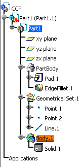
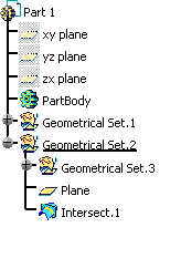
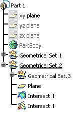
Before You Start
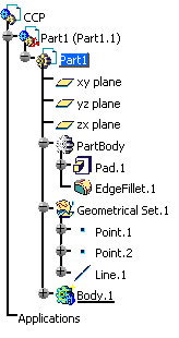
This scenario uses two products: one containing the geometrical data to be copied (named "CCP") and the other used as the target object. CCP looks like this:
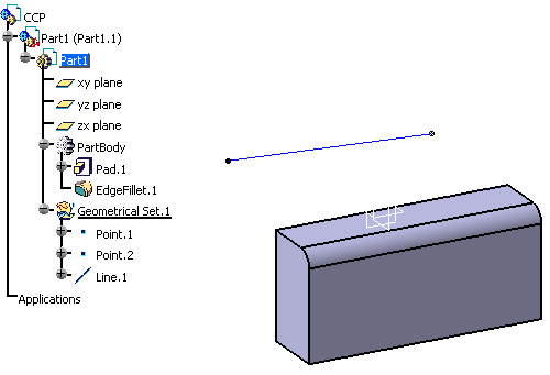
- Part body
- Body.n (provided that it contains a solid feature such as a pad)
- Pad
- Sketch
- Geometrical set
- Points, lines, planes, etc., i.e. surface elements
- Constraints
- Parameters.
- As specified in Part document: the object is copied as it has been created but generally without its design specifications. For instance, surface features cannot be copied with their design specifications whereas pads can
- As Result With Link: the object is copied without its design specifications and is linked to the original object. In other words, whenever the original object is modified, the copied object may be manually updated to reflect the changes
- As Result: the object is copied without its design
specifications and without any link with the original object. It is
considered as an autonomous entity.
However, note that as far as ordered geometrical sets, hybrid bodies and part bodies are concerned, only the final result is copied - As Specified in Product Structure: the source instance is duplicated and the link to the source reference is kept. A new instance of the source is created and it has the same reference as the source. For detailed information, refer to "Paste Special" in the Version 5 - Product Structure User's Guide
- As Specified in Assembly
- As Result With Link Flat Mode (to paste a flattened object).
|
Features |
Part body | Body.n | Pad | Sketch |
Geom. set |
Surface feature | Parameter | Constraint |
|
Formats |
||||||||
| As specified in Part document |
|
|
|
|
|
|
|
|
| As Result With Link |
|
|
|
|
|
|||
| As Result |
|
|
|
|
|
|||
| As Specified in Assembly | ||||||||
| As Specified in Prod. Structure | ||||||||
| As Result With Link Flat Mode |
|
Pasting Solid Objects Using the Specification Tree
-
Select PartBody.
-
Select Edit > Copy.
-
Select Edit > Paste Special. The Paste Special dialog box opens and displays three paste options, detailed hereafter:
Pasting As Result
A solid is created under:
- a body named "Body.n", n being incremented according to the number of existing bodies:
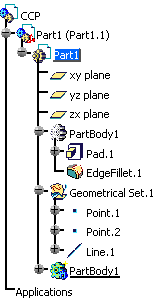
- a body with an identical name if the original body has been previously renamed via Edit > Properties > Feature Properties:
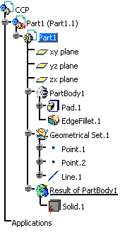
- when the In the main object check box is selected in Tools > Options > Infrastructure > Part Infrastructure > Display, a solid is created under a body named "Result of BodyUserName" if the original body has been renamed:
This solid can, in turn, be copied on the condition that it is pasted onto a mechanical body and in the first position in the mechanical body (in case there is no body to paste the solid, a new body is created). Note that wif you select a location for the copied element, the result is the same.
However, if you paste "PartBody" As Result in a new CATPart document, the result is as follows:
The reason is that pasting objects such as ordered geometrical sets, part bodies or hybrid bodies As Result means that only the final result (a solid named "Solid.1" in the example above) is copied.
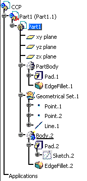
Pasting As specified in part document
The object is copied with its design specifications, each component number being incremented:
In case of a solid with surface features, we recommend that you use the multi-selection to select individually each object to be copied. In order to make sure to copy all the desired objects, you can select Tools > Parent Children or Tools > Show Historical Graph to display the genealogical relationships between the different components.
Another method is to use PowerCopies. For more information on using PowerCopies, refer to Version 5 Generative Shape Design User`s Guide - Managing Power Copies.
Pasting As Result With Link
The object is copied without its design specifications. The pasted object is identified by one of these two symbols:
- a blue arrow indicates that the geometry has been pasted to the same document and is still linked to the original object.
The pasted object can be manually updated whenever the original object is modified. This copy is located under a body named "Body.n", "n" being incremented according to the number of existing bodies: If the original body has been previously renamed by the user via Edit > Properties > Feature Properties > Feature Name and if the In the main object check box is selected in Tools > Options > Infrastructure > Part Infrastructure > Display, the copy is located under a body named "Result of BodyUserName".
- a circle indicates that the geometry has been copied from a document different from the document to which it has been pasted.
For more information about the various referenced geometry symbols, refer to Symbols Used in the Specification Tree.
More about solids pasted As Result With Link
- When opening a document containing a body pasted As Result With Link, the corresponding symbol displayed in the specification tree is
. This symbol means that the pointed document has been found but not loaded. To correct this, right-click the object in the tree then select Load, or select Edit > Links... then click Load.
The symbol will then change toto indicate that the object has been copied from a document different from the document it has been pasted to and that it is synchronized with its reference.
After this synchronization step, the document containing the body pasted As Result With Link needs to be updated to integrate the changes from the pasted body. This update requires to open the document first and then, to update it.
If the updated document contains itself a body pasted As Result With Link in another document, the same mechanism applies to the latter, i.e. synchronization step then, a second update of the document.- If you deactivate a solid pasted As Result With Link, its symbol in the specification tree changes from
to
to indicate that the external link is deactivated (the solid is isolated just like a datum) but not the geometry.
- When a feature is pasted As Result With Link, the color (if any) is kept. However, note that this color is not considered as a synchronizable information: the color is only copied when the feature is pasted and therefore, you will not be able to update it if the color of the original feature is modified.
![]()
Pasting Surface Objects Using the Specification Tree
-
Select Point.1.
-
Select Edit > Copy.
-
Select Edit > Paste Special. The Paste Special dialog box opens and displays three paste options:
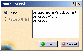
The result depends on the paste location you selected before running the Paste Special... command:
Pasting onto a part body
If you PartBody, the point is copied:
- under the current body (if suitable). The number of the copy is incremented, whatever the paste option you choose
- if no part
body is suitable, the point is pasted under the first available
geometrical set (if there is one). The copy number is incremented
accordingly:
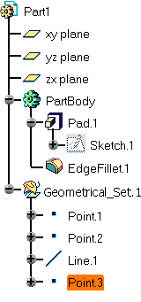
- If no geometrical set exists, a new geometrical set is created to paste the point.
Pasting without specifying the paste location
If no paste location has been previously selected, the result is identical to the one detailed in Paste onto a part body, whatever the paste option:
- the point is copied under the current geometrical set (if suitable). The number suffixing the name is incremented accordingly.
- if the current geometrical set is not suitable, the point is pasted under the first available geometrical set (if there is one).
- if no geometrical set exists, a new geometrical set is created to paste the point.
Pasting to a new document using As specified in Part document
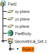
If you copy the point to a new document using As specified in Part document:
- the point is copied under the current body (if suitable), otherwise
under the
first available geometrical set if there is one. The number
suffixing the name is incremented accordingly:

- under a new geometrical set if no geometrical set exists:
Warning
- An external reference cannot be pasted As specified.
If you want to paste an internal import, make sure that the geometry has been copied with its reference, otherwise you will not be able to paste it - An element aggregated by a geometrical feature cannot be
pasted As specified. In the example below, if you
copy Split.2 then paste it onto Geometrical Set.2, the
Paste Special dialog box only displays As Result
and
As Result With Link. The reason is that Split.2 is not
an autonomous element and belongs to Split.1.
However, if you copy Split.1 with Split.2, you can paste both elements As specified (as shown in the picture to the right) because Split.1 and Split.2 are considered as a single entity: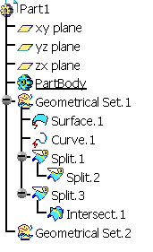
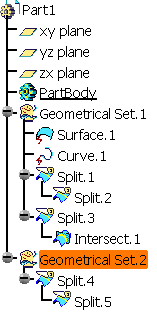
If you copy then paste Split.1 As Result (or As Result With Link), only Split.1 is pasted.
Pasting to a new document using As Result With Link
If you select As Result With Link then paste to a new document:
- the point is copied under
a node named "External References" if you select the Part Body, the
part itself or no destination at all:
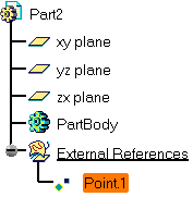
- under the geometrical set if you select a geometrical set:
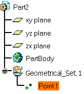
In both cases, the pasted element contains a green symbol indicating that it has been copied from a document different from the document it is pasted to and that it is synchronized with its reference. 
- Copy > Paste is an explicit action. As a consequence, a feature pasted "As Result With Link" can be pasted as an external reference but will always appear in Show mode, even if the Create external references in Show mode check box is not selected in Tools > Options > Infrastructure > Part Infrastructure > General
- When a feature is pasted As Result with Link, the color (if any) is kept. However, note that this color is not considered as a synchronizable information: the color is only copied when the feature is pasted and therefore, you will not be able to update it if the color of the original feature is modified.
Pasting to a new document using As Result
If you select As Result then paste to a new document, the point is copied under:
- the current body (if suitable), or under the first available geometrical set if
there is one (the object number is incremented if an object
with the same name already exists):
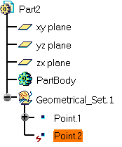
- under a new geometrical set if no geometrical set exists:
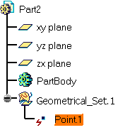
In both cases, the pasted element contains a red symbol indicating that the pasted element is isolated, i.e. it can no longer be edited. Note: pasting a geometrical set As Result is recursive, i.e. all the elements located below the geometrical set are also be pasted.
In the following example, when copying then pasting "Geometrical Set.1" As Result onto "Part1", you can see that the resulting copy (named "Geometrical Set.1") contains all the elements included in Geometrical Set.1: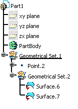
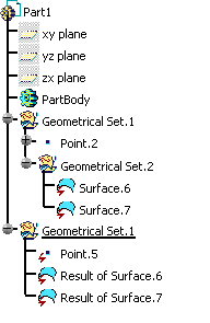
If the In the main object check box is selected in Tools > Options > Infrastructure > Part Infrastructure > Display, the "Result of" prefix is added to the resulting copy. In our example, it would be named "Result of Geometrical Set.1".
More about pasting surface objects
- If a surface or wireframe feature has
been renamed via Edit > Properties > Feature Properties prior
to copying it, this feature is pasted as "Result of SurfaceUserName"
when using As Result or As Result with Link, and
as "Copy of SurfaceUserName" when using As Specified in Part
Document
only when the In the main object check box is selected
in Tools > Options > Infrastructure > Part Infrastructure > Display.
This "Copy of ..." or "Result of ..." prefix is used only if the document in which the element is pasted already contains a feature renamed "SurfaceUserName". If the name "Copy of SurfaceUserName" conflicts with the name of an existing feature, the system will try to name the pasted feature "Copy (2) of SurfaceUserName" and if this new name is already used, it will try "Copy (3) of SurfaceUserName" and so on.
If the user pastes in an empty CATPart, the name "SurfaceUserName" does not conflict with any other name and thus, can be kept as is.
When the No name check or Under the same tree node check box is selected, no prefix is added.
- If you copy then paste As
Result a surface element which is not a point, a line, a surface or
a plane, the result will be a line, a curve, a circle or a surface
according to the geometrical dimension and the type of the element.
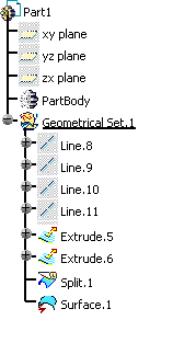
In the example below, when "Split.1" is copied then pasted As Result onto "Part1", the resulting element is a surface ("Surface.1"):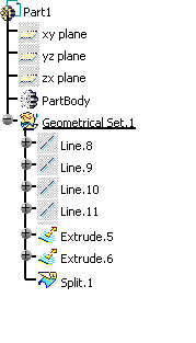
If the dimension cannot be determined (this is the case for features containing several geometrical domains with a different dimension such as a point and a line or a line and a plane), the result is a 3DDatum.
In the example below, when "Intersect.1" (which contains a point and a line) is copied then pasted As Result (or As Result With Link) onto "Part1", the resulting element is a 3DDatum identified by a yellow symbol representing a surface, a curve and a point:
- If you paste As Result With Link
a surface element which is not a point, a line, a surface or a plane,
then the result is a curve or a surface according to the geometrical
dimension.
The result can be neither a line, nor a circle because it is not possible to synchronize a line or a circle with a general curve.
![]()
Pasting Contextual Features and Surface Objects Using the Geometry Area
In our example, we assume there are two documents: CCP.CATProduct, containing the elements to be copied, and the target document.
Pasting contextual features
-
In the CCP.CATProduct document, select EdgeFillet.1.
-
Select Edit > Copy.
-
Access the target document.
Three results might occur depending on the paste location and the elements contained in the target document: - if you paste the edge fillet onto a part body with no pad, an error occurs since a fillet needs an element of type "Pad" to be pasted to.
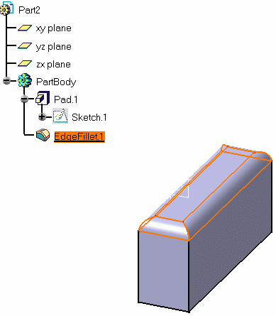
- if you paste it onto a pad with a sketch and if you select one or more edges prior to pasting, the edge fillet is correctly pasted:
- if you paste it onto a pad with a sketch without selecting any paste location, an error occurs becausee several edges exist and the following dialog box is displayed:
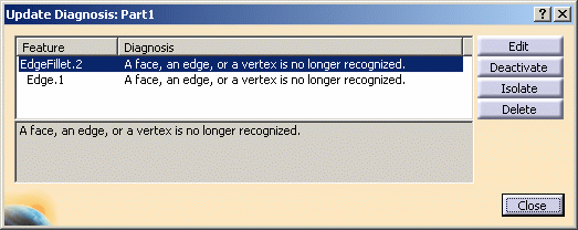
- Click Edit then OK to close the dialog box.
- In the Edge Fillet Definition dialog box that opens, select the objects to fillet as well as the radius value and the propagation. (Refer to the Version 5 - Part Design User's Guide for more information on creating an edge fillet). Note that if you select the line Edge.1, the Edit dialog box appears instead of the Edge Fillet Definition dialog box to let you select the element onto which the fillet should be pasted.
- Click OK to validate to paste the edge fillet.
Note that:
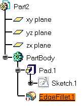
- clicking Deactivate results in the deactivation of the edge fillet representation, i.e. it appears in the specification tree only with the following symbol:
- clicking Delete amounts to clicking Close.
As far as contextual features with multiple entries are concerned, we recommend that you use PowerCopies to copy/paste multiple elements or single elements taking multiple features as entry specifications. For more information on using PowerCopies, refer to the Version 5 Generative Shape Design User`s Guide - Managing Power Copies.
![]()
Pasting surface objects
-
In the CCP.CATProduct document, select Line.1.
-
Select Tools > Parent/Children:
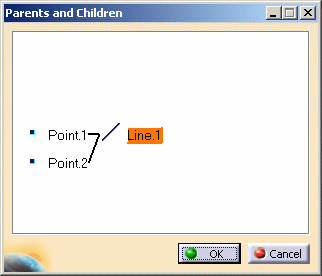
This window displays the dependencies between the elements to be copied. For detailed information on this command, refer to the Version 5 Generative Shape Design User`s Guide - "Parents and Children".
-
Once these dependencies are displayed, you can either select only the necessary elements (using the multi-selection) or select the whole open body before pasting them using Edit > Paste Special.
General Rules for Managing the Paste Destination
- if the paste destination you select is not appropriate, an error window is displayed. For instance, pasting directly in an "External References" node is forbidden
- if the paste destination is a geometrical feature, the element is pasted after the selected geometrical feature (if applicable)
- if the paste destination is a body (e.g. part body, geometrical set), the application pastes the element in the body and in last position
- if the paste destination is a part
- for a geometrical feature, the application tries to find a destination based on the current feature
- for a body or a set, the element is pasted under the part
- if no paste destination has been selected or if you are working with power copies, the application tries to paste the element in or after the current feature.
The rules that apply when creating geometrical features also apply when pasting them as shown in the following table:
|
Can be pasted in |
Part body (created before V5R14) |
Part body (created from V5R14 onwards) |
Geometrical set |
Ordered |
| Geometrical set feature | ||||
| Part body | No | No | No | No |
| Geometrical set | Yes | No | Yes | No |
| Ordered geometrical set | No | Yes | No | Yes |
- if the geometrical set was located under the part as defined in the power copy, the feature is pasted under the part
- if the geometrical set was a sub-geometrical set (i.e. located under a body or under another set), the feature is pasted according to the current feature.
How Are Sub-Elements Copied?
- if you select a sub-element such as a face, an edge or a vertex in
the geometry then copy it, the copy will include the first element that
can be copied and not only the sub-element itself.
For instance, if you copy a face of a pad, the whole pad will be included in the copy - you cannot copy a publication of a sub-element (edge, face or vertex). If you try to do so, an error message will appear.
![]()
