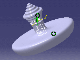

Configuration 3
of KwrProfilesDesignTable.xls
applied to
KwrBottleProfiles.CATPart
You now have a preliminary document. How are you going to warp the profile of the bottle and search for other shapes? How can you capture all the data fulfilling the requirements? If need be, how are you going to proceed to refine your design in order to obtain a given volume? Using a design table is a way to capture your design intent and modify your document through an external file. In the scenario below, we first deform the bottle shape interactively by manipulating the control points of the spline, then we create and enrich a design table from the data of the documents fulfilling the requirements.
Open the KwrVolumeCheck.CATPart document.
Double-click the Sketch.1 feature and manipulate the D and E control points to deform the spline. See Appendix: Creating a Deformable Revolution Body for a definition of the D and E control points. As soon as you deform the spline:
The document color changes (by default it turns to red).
In the specification tree, an update icon is displayed on the root feature and on the formula.
Update the Part by double-clicking the root feature in the specification tree or in the geometry area.
Access the Knowledge Advisor workbench by double-clicking the formula in the specification tree.
Click the Measure Update icon (![]() )
to update the formula. If the recalculated volume does not satisfy the
requirements, a message box is displayed informing you that the volume is out
of range and the check icon turns red. Otherwise, the check icon turns
green.
)
to update the formula. If the recalculated volume does not satisfy the
requirements, a message box is displayed informing you that the volume is out
of range and the check icon turns red. Otherwise, the check icon turns
green.
Redo these interactions until you obtain a bottle satisfying both your style criteria and your volume requirements. As soon as you find the right profile, follow the method below to create a design table intended to store the data related to this profile as well as the data corresponding to other profiles.
Open the KwrVolumeCheck.CATPart document and save it under a new name.
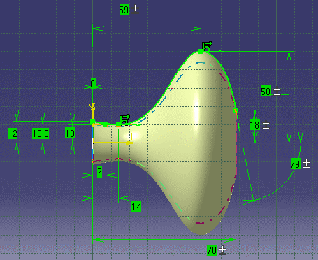
In the renamed document, access the Sketch.1 feature and add the xD,yD, xE and yE offset constraints on the D and E control points. The constraints named x are defined along H while those named y are along V. Add a tangency constraint on E with respect to H as on the figure below and name it TangE. Refer to Appendix: Creating a Deformable Revolution Body for the definition of the control points. The figure below is an example of a valid shape.
 |
If need be, update the document and the formula.
In the standard toolbar, click the Design Table
icon (![]() )
to create a design table.
)
to create a design table.
In the Creation of a Design Table dialog box, check the Create a design table with current parameter values box. Click OK. The Select parameters to insert dialog box is displayed.
Select the xD, yD, xE, yE and TangE parameters in the Parameters to insert list. Use the right arrow to move them to the Inserted parameters list. Click OK.
In the Select the Pathname of the File to be Created dialog box, specify the pathname of an .xls file to store the design table, and click Open. A single row design table similar to the one below is displayed.
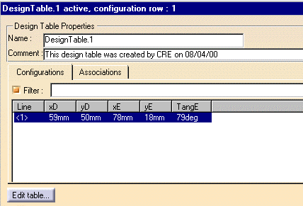 |
Edit the created design table by clicking the Edit table... button. The Microsoft Excel application is started. A single row table with the xD, yD, xE and yE and TangE parameter values is displayed. Click OK in the design table dialog box to add the created design table to your document. Save and close this document.
Go back to KwrVolumeCheck.CATPart, edit the sketch and search for another profile. As soon as you think a profile is worth saving, edit the control points and carry forward the edited values to the Excel table you have just created. Each time you do this, you add a new row to the design table.
After the data of all the profiles to be stored have been added to the Excel table, close this .xls file and re-open the renamed document. Re-edit the design table, select one by one each design table configuration in order to display the various shapes on screen.
If you enrich the created design table with the data below:
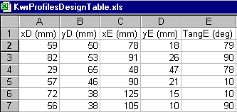 |
This is what you get on screen when this design table is edited in the renamed document.
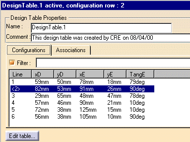 |
The design table above is provided in the KwrProfilesDesignTable.xls sample. The bottle shape corresponding to each configuration of this design table is depicted by the figure which starts each chapter of this part.