Options

Display a warning when adding properties to a material
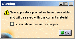
If this option is selected, it means that whenever you want to add properties to a material (by double-clicking it then choosing the Analysis or Drafting tab for example), a warning message is issued to let you know that the material has been modified when you accessed the Analysis or Drafting properties:
Use Link mode by default when applying a material
If this option is selected, it means that the selected material is mapped as a linked object and thus, will be automatically updated to reflect any changes to the original material in the library.
Note: the link mode is activated whichever method you use to apply the material, i.e. the Apply Material command or drag & drop capabilities. For more information, refer to "Applying Materials" in the Version 5 - Real Time Rendering User`s Guide.
![]() By default, this option is cleared.
By default, this option is cleared.
Use Force mode as the default inheritance mode
If this option is selected, it means that the force inheritance mode is activated, i.e; a material is forced when it is applied onto parts, products, bodies or surfaces in order to make it visible even if a father material propagates.
For more information on inheritance modes, refer to "Setting Priority between Part and Product" in the Version 5 - Real Time Rendering User`s Guide.
![]() By default, this option is cleared.
By default, this option is cleared.
Desynchronize visualization when modifying material attributes
If this option is selected, it means that the material properties is modified independently from the visualization and thus, this avoids visualization refresh which can take a long time when working on big models.
![]() By default, this option is cleared.
By default, this option is cleared.
Open the catalog in read-write mode when applying a material
If this option is selected, it means that, for any applied material, you can open and modify the corresponding material catalog.
![]() By default, this option is cleared.
By default, this option is cleared.
Material Parameters

Create a material parameter when creating a part, a body or a surface
If this option is selected, it means that a material parameter will be
automatically created for any part, body or surface you create (either
using File > New or the Insert command), even if no
material is mapped onto it.
Activating this option also means that a parameter entitled "Material=None"
(or "Material" if you decided not to activate the display of the parameter
value in Tools > Options > General > Parameters and Measure >
Knowledge) appears in the specification tree.
![]() By default, this option is cleared.
By default, this option is cleared.
Create a link to the catalog when modifying a material parameter
If this option is selected, it means that a linked material
is created when modifying a mapped material using Knowledgeware
capabilities.
Do not forget to select the Parameters check box in Tools >
Options > Infrastructure > Part Infrastructure > Display to visualize
the Material parameter.
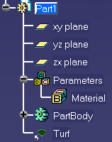
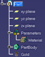
In the two examples below, the Material parameter was selected in the specification tree then modified via the Edit Parameter dialog box (using Material object > Definition):
 |
 |
| Option activated Material applied as a linked material |
Option cleared Material applied as a non-linked material |
Default Material Catalog Path

The selected material catalog supersedes the one defined in the
CATStartupPath environment variable and thus, will be retrieved when
selecting Default Material Catalog from the Library
dialog box.
Depending on the document environments (i.e. the method to be used to access your documents) you allowed in the Document tab, an additional window may appear simultaneously to the File Selection dialog box to let you access your documents using an alternate method:
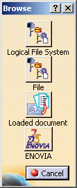
If you want to access your texture files using DLNames, for instance, click the Logical File System button: this opens a specific dialog box dedicated to the DLName environment.
For detailed information on this dialog box, refer to Opening Existing Documents Using the Browse Window.
Environment Image File

To do so, enter the path to the user-defined environment or click the
Note that depending on the document
environments you allowed in the Document tab, the Browse
window may appear simultaneously to the File Selection dialog
box to let you access your documents using an alternate method.
For detailed information, refer to
Opening Existing Documents Using the Browse Window.
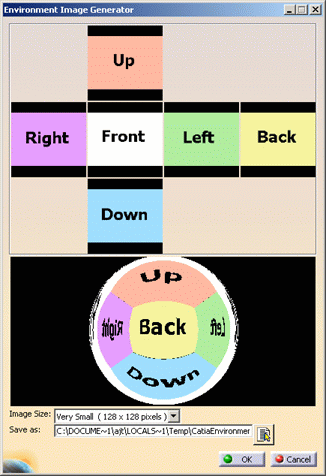
Click the Environment image generator
![]() button to open the Environment Image Generator dialog box (this
icon appears only when working with a Real Time Rendering 2 license):
button to open the Environment Image Generator dialog box (this
icon appears only when working with a Real Time Rendering 2 license):
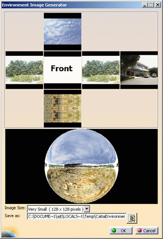
The resulting environment is displayed on the environment map as shown below:
- Very Small (128 x 128 pixels)
- Small (256 x 256 pixels)
- Medium (512 x 512 pixels)
- Large (1024 x 1024 pixels)
- Very Large (2048 x 2048 pixels).
Once the image is generated, enter its name and path in the Save as
box or click the Browse Directories
![]() button to open the File Selection dialog box which lets you
browse your folders to the desired location.
button to open the File Selection dialog box which lets you
browse your folders to the desired location.
Note that depending on the document
environments you allowed in the Document tab, the Browse
window may appear simultaneously to the File Selection dialog
box to let you access your documents using an alternate method.
For detailed information, refer to
Opening Existing Documents Using the Browse Window.
Click OK to validate and go back to the Material tab.