![]()
Select the Photo/Video tab, which is divided up into areas.
Parameters in this area... Allow you to customize... Simulation at material removal simulation at program of Part Operation level Video Video material removal simulation options Photo Photo material removal simulation options Performance settings that influence performance Color color during material removal simulation Positioning Move allowed tool axis variation between two operations
Simulation at

Select the desired
option to perform material removal simulation at either Program or Part
Operation level.
Depending on the selected level, simulation begins either from the start of
the manufacturing program or from the start of the Part Operation.
Best performance is obtained with Program level.
![]() By default, the Program level option is selected.
By default, the Program level option is selected.
Video

Stop at tool change
Select the Stop at tool change check box if you want the Video simulation to stop each time a tool change is encountered in the program.
![]() By default, this check box is not selected.
By default, this check box is not selected.
Collision detection
Select the desired Collisions detection option to:
- ignore collisions during the Video simulation
- stop the Video simulation at the first collision
- continue the Video simulation even when collisions are detected. In this case, you can consult the list of collisions at any time during the simulation.
Best performance is obtained when collisions are ignored.
![]() By default, the Ignore option is selected.
By default, the Ignore option is selected.
Touch is collision
Select the Touch is collision check box if you want touch (or contact) type of collision to be detected.
![]() By default, this check box is selected.
By default, this check box is selected.
Multiple Video result on program
Select the Multiple Video result on program check box if you want to store video results on more than one operation in the program.
![]() By default, this check box is not selected.
By default, this check box is not selected.
Photo

Select the desired Fault box type for examining remaining material or gouges:
- Transparent: to display a transparent bounding box
- Wireframe: to display a wireframe bounding box
- None: if no bounding box is required.
![]() By default, the Wireframe option is selected.
By default, the Wireframe option is selected.
Select the check box to compute all information at the picked point.
![]() By default, this check box is not selected.
By default, this check box is not selected.
Best performance is obtained when Fault box is set to None and the Compute all information at picked point check box is not selected.
Performance

Tool and faceting
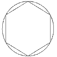
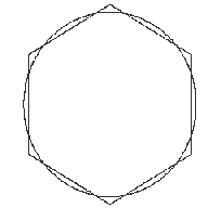
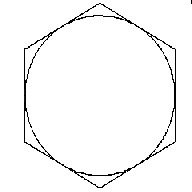
There are three methods of tool faceting used in Video simulation:
Standard, Smaller and Larger.
The number of facets for a tool representation is determined by the chord
deviation that is set for the tool diameter (0.005% of the tool diameter).
- Smaller: The picture shows a rough approximation of a tool
with six facets. Note that the chord deviation is always inside the
actual circle, and that the points are always on the circle (accurate).

This is the most accurate method for the Arc through Three Points command.
- Standard: The picture shows a rough approximation of a
tool with six facets. Note that the chord deviation is partly inside and
partly outside the actual circle, and that the points are not always on
the circle.

This is the best method for material removal simulation.
However, this is not suitable for the Arc through Three Points command. - Larger: The picture shows a rough approximation of a tool
with six facets. Note that the chord deviation is outside the actual
circle, and that the points are not on the circle.

This is not suitable for the Arc through Three Points command.
However, it can be useful for gouge detection.
![]() By default, the Standard option is selected.
By default, the Standard option is selected.
Photo resolution
Best performance is obtained when the Photo resolution is set to 0. In
this case, a detailed simulation of a portion of the part can be obtained
using the Closeup command.
Increasing the resolution improves machining accuracy and gives a very
detailed simulation. However, this requires increased memory and
computation time.
![]() By default, this resolution is set to 0.
By default, this resolution is set to 0.
Tool axis interpolation angle (5-axis only)
Specify the maximum angle that the tool axis is allowed to vary between
two consecutive points.
Best performance is obtained for an angle of 10 degrees. Decreasing the
angle improves the precision of the simulation. However, this requires
increased memory and computation time.
![]() By default, this angle is set to 1degree.
By default, this angle is set to 1degree.
Optimized rendering for Video
Select the Optimized rendering for Video check box to obtain
an optimized rendering that improves Video simulation performance.
Otherwise, more realistic colors are obtained with a slightly degraded
performance. Milling, drilling, and turning operations are supported .
![]() By default, this check box is selected.
By default, this check box is selected.
Color

Set the tool (and associated machined area) color to be the same as or different from the last tool, or have different colors for all tools. Best performance is obtained with same colored tools.
![]() By default, the All different option is selected.
By default, the All different option is selected.
Assign colors to the different tools using the associated color combo.
Assign colors to tool holders, parts, and fixtures using the associated color combos.
Positioning Move

Set the Maximum tool axis variation that is to be allowed between the end point of an operation and the start point of the next operation. If the tool axis varies by an amount greater than the specified value, then the tool is positioned at the start of the following operation.
![]() By default, this angle is set to 1degree.
By default, this angle is set to 1degree.