This page deals with the following settings:
3D Fasteners All Display Options
Click the Unset All button to uncheck all the
options, except for the Shape Representation option. Similarly click the
Set All button to check all options.
These options apply to all the fasteners contained in the product.
Shape
Click the Show button to visualize the fastener's shape.
ID
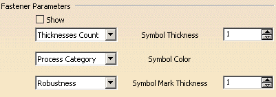
Fastener Parameters
Click the Show button to visualize the fastener's shape.
Associating a symbol to a specification
-
a process type (by default): the symbol is displayed according to the symbol code assigned to the Fastener Process Type in the standard file. By default, if no symbol is assigned to the process type in standard, or if there is no imported standard, the symbol is
 (101)
(101) -
an unspecified type (Unspec): the default symbol
 is displayed. It can be modified through the Properties
contextual command.
 -
the thickness count: the symbol is displayed according to symbol code assigned to the Thickness Count in the standard file.
By default, if no symbol is assigned to the thickness count in standard, or if there is no imported standard, the symbol is:
for 1 thicknesses (1)
for 2 thicknesses (2T)
for 3 thicknesses (3T)
for 4 thicknesses (4T)
for more than 4 thicknesses
- None: no symbol is visualized.
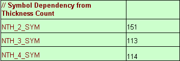
For 2T:
For 3T:
For 4T:
Associating a color to a specification
-
a process category (by default): the color is displayed according to the color code assigned to the Fastener Process Category in the standard file.
By default, if no color is assigned to the Process Category or no standard is imported, the default color is:
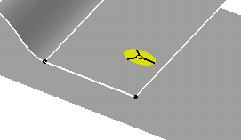
Yellow for Welding
Cyan for Adhesive
Magenta for Sealant
Green for BiW Mechanical
White for Unspecified
-
an unspecified type (Unspec): a default color is displayed:
Yellow for Welding
Cyan for Adhesive
Magenta for Sealant
Green for BiW Mechanical
White for Unspecified
- None: no symbol color is visualized.
Associating marks to the specification
- Robustness
- Regulation
- Finish
- None
Note that:
- 1 is for assigning a mark
- 0 is for assigning no mark
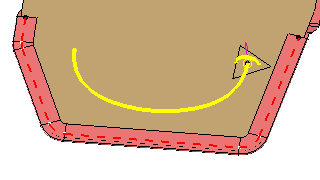
- For Robustness parameter ("Safety") enter the C value.
- For Regulation parameter ("Norm A") enter the A value.
- For Finish parameter ("Class A") enter the A value.
Fastener Axis Orientation
- K Axis only:
- if checked, only the K axis is visualized on the fastener's
location.
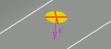
- if unchecked, a trihedron showing the fastener's normal (K),
tangent (I) and normal to the tangent (J) is visualized are visualized
on the fastener's location.
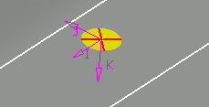
For a curve bead, the location corresponds to the start point.
- if checked, only the K axis is visualized on the fastener's
location.
- On each Discretization Point: for a curve bead, it enables
to visualize the trihedron on each discretization point.
- if checked: the K axis is visualized on each discretization point
of the curve bead.

- if unchecked, the trihedron is visualized on each discretization
point of the curve bead.
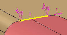
- if checked: the K axis is visualized on each discretization point
of the curve bead.
Support Contact Zone Material Orientation
Contact Zones
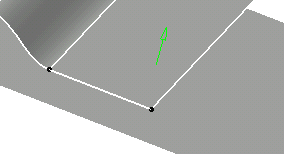
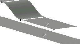
Show Projected Points
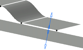
Show Material Orientation
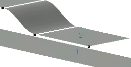
Show Thickness Stack-Up Order
For further information, refer to Ordering Thickness Crossing Criteria from the Report chapter.
- You can define the thickness and the material orientation for a GSD
feature using the Thin Parts Attribute command in the Generative
Shape Design workbench.
Refer to the Applying a Thickness chapter in the Generative Shape Design documentation. - The options listed above can also be accessed using the fasteners'
properties via the contextual menu.
Refer to the Editing the Fasteners' Properties chapter.
- when selecting at least one of the options contained either in the Support Contact zone Material Orientation or in the Contact Zones within the Properties dialog box,
- and when selecting Tools > Options > Mechanical Design > Assembly Design > General, the Automatic Switch to Design Mode option,
then all joint components are automatically switch to Design mode.
The Automatic Switch to Design Mode option must be activated
to visualize the desired options.
If you do not wish to have all joint components automatically switch to
Design mode, then uncheck the options mentioned above.
![]()
