Feature Dictionary Settings
|
|
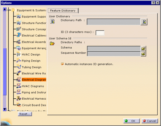
This file explains how to set the options for the user dictionary and schema Id. | |||||
|
|
|
|||||
User Dictionary |
||||||
|
|
The dictionary contains object basic classes such as:
equipments, sockets, plugs, switches, cables, etc. These objects have standard properties: type, part number, etc. According to you needs, you may want to define more properties such as subtype classes, and other specific attributes:
This is done using the
Feature
Dictionary Editor
The classes, subclasses and their properties are saved in a document
with a CATfct extension.
In the User Dictionary File Name field, only enter the file name and extension.
|
|||||
|
|
In order to access the user subclasses and properties defined in the .CATfct file, always reference an existing .CATfct file. If a .CATfct file has been used to create data, it must not be deleted to preserve the data consistency. |
|||||
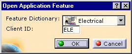
Client ID |
||||||
|
|
The Client ID is defined in the Feature Dictionary Editor
as a protection on the CATfct file, before creating the user dictionary and
the subclasses.
In the ID field, enter the same three characters: |
|||||
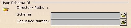
User Schema ID |
||||||
|
|
Within a project, it is possible to define naming rules for the
schematic objects. They are used to set automatically the Reference
Designator attribute on electrical components. These rules (Schema ID)
are saved in xml files and stored together in specific directory. It is the
path to this directory that you indicate in the first field (Schema)
of the frame below. The Sequence Number is assign automatically provided that the file server is stored in a directory shared between all the users working on the project. Enter the path to this directory in the second field (Sequence Number) of the frame below You can decide then to use the naming rules you have defined or not.
|
|||||
![]()