This page deals with the following categories of options in the Geometry tab:
Geometry
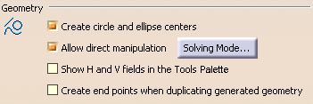
Create circle and ellipse centers
Specify whether you want to create centers when creating circles or ellipses. Clear this check box if you do not need to create circle and ellipse centers.
By default, this option is selected.
Allow direct manipulation
Select this check box to be able to move geometry using the mouse. When moving geometry, you can move either the minimum number of elements, the maximum number of elements, or still the minimum number by modifying the shape of elements, if needed.
By default, this option is selected.
Additionally, click the Solving mode... button to configure manipulation.
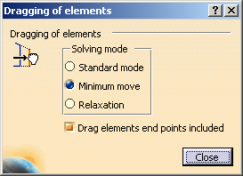
The dialog box that appears offers the following options as regards the solving mode:
Standard mode
You move as many elements as possible and also respect existing constraints.Minimum move
You move as few elements as possible and also respect existing constraints.Relaxation
You move elements by re-distributing them over the sketch, globally speaking. This method solves element moving by minimizing energy cost.Furthermore, you can choose to drag elements along with their end points by selecting Drag elements end points included.
By default, Minimum move and Drag elements end points included are selected.
Show H and V fields in the Tools Palette
Select this check box to show the H and V fields in the Tools Palette when creating 2D geometry or when offsetting elements. Leaving the option unselected enables you to directly enter the value corresponding to the type of element you are creating: for example, the length when creating a line, the radius when creating a circle or the offset value when offsetting elements.
When a command (such as the Point creation command) does not have any parameters other than H and V, then these two fields will remain in the Tools Palette, whether you select this option or not.
By default, this option is not selected.
Create end points when duplicating generated geometry
Select this check box if you want to create end points when duplicating geometrical elements that were generated from the 3D.
By default, this option is not selected.
Constraints creation

Create detected and feature-based constraints
Select this check box if you want the geometrical or dimensional constraints detected by the SmartPick tool to be created.
This option is also available in the Tools toolbar through Create detected constraints
. If you leave this check box unselected, Create detected constraints will be inactive by default. You will be able to activate it at any time.
By default, this option is not selected.
SmartPick... (button)
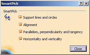
As you create more and more elements, SmartPick detects multiple directions and positions, and more and more relationships with existing elements. This may lead to confusion due to the rapid highlighting of several different detection possibilities as you point the cursor at different elements in rapid succession. Consequently, you can decide to filter out undesired detections by clicking the SmartPick... button.
The SmartPick dialog box provides these options:
- Support lines and circles
- Alignment
- Parallelism, perpendicularity and tangency
- Horizontality and verticality
Clear the check boxes corresponding to the elements you do not wish to detect when sketching.
Clearing all check boxes in the SmartPick dialog box disables SmartPick completely. This will be particularly useful when your screen is full of elements: in this case, disabling SmartPick lets you concentrate only on the geometry.
By default, all options are selected.
Constraints Display
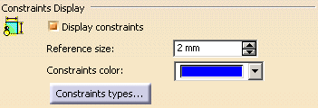
Display constraints
Select this check box to visualize the logical constraints specific to the elements. Note that if the Display constraints option is cleared, the other options in this category are not available.
By default, this option is selected.
Reference size
Specify the size that will be used as a reference to display constraints symbols. Changing this reference size will modify the size of all constraints representations.
By default, the reference size is 2 mm.
Constraints color
Choose the color that will be used to display constraints.
By default, the color for constraints is blue.
Constraints types... (button)
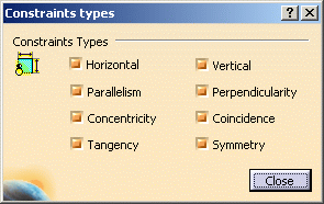
Click this button to define which types of constraints you will visualize as you create the geometry.
The Constraints types dialog box provides these options:
- Horizontal
- Vertical
- Parallelism
- Perpendicularity
- Concentricity
- Coincidence
- Tangency
- Symmetry
Clear the check boxes corresponding to the types of constraints you do not want to visualize as you create the geometry.
By default, all options are selected.
Colors

- Graphical properties
Colors that can be modified. These colors can therefore be modified using the Tools > Options dialog box.
OR
- Constraint diagnosis
Colors that represent constraint diagnoses are colors that are imposed to elements whatever the graphical properties previously assigned to these elements and in accordance with given diagnoses. As a result, as soon as the diagnosis is solved, the element is assigned the color as defined in the Tools > Options dialog box.
Visualization of diagnostic
Select this option if you want over-constrained, inconsistent, not-changed or iso-constrained elements to be identified using specific colors.
By default, this option is selected.
Then, click the Colors... button to configure these colors.
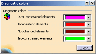
In the dialog box that appears, you can configure colors for the following types of elements:
Over-constrained elements
The dimensioning scheme is over-constrained: too many dimensions were applied to the geometry.Inconsistent elements
At least one dimension value needs to be changed. This is also the case when elements are under-constrained and the system proposes defaults that do not lead to a solution.Not-changed elements
Some geometrical elements are over-defined or not-consistent. As a result, geometry that depend(s) on the problematic area will not be recalculated.Iso-constrained elements
All the relevant dimensions are satisfied. The geometry is fixed and cannot be moved from its geometrical support.
By default, colors are configured as shown above.
Other color of the elements
Click the Colors... button to configure the colors of other elements.
In the dialog box that appears, you can configure colors for the following types of elements:
Construction elements (For pre-V5 R11 drawings)
Specifies the color used for construction elements.
A construction element is an element that is internal to, and only visualized by, the sketch. This element is used as positioning reference. It is not used for creating solid primitives.
This option applies only to drawings created with versions prior to V5R11. SmartPick
Specifies the color used for SmartPick elements and symbols.
By default, colors are configured as shown above.
