This task explains how to access company standards files in order to access and define design tables.
Open a new document.
-
Click the Sheet Metal Parameters icon
 .
.
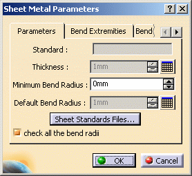
The Sheet Metal Parameters dialog box opens.
-
Select the Sheet Standards Files... button. The File Selection window is displayed.
-
Indicate the path to the Sheet Metal table.
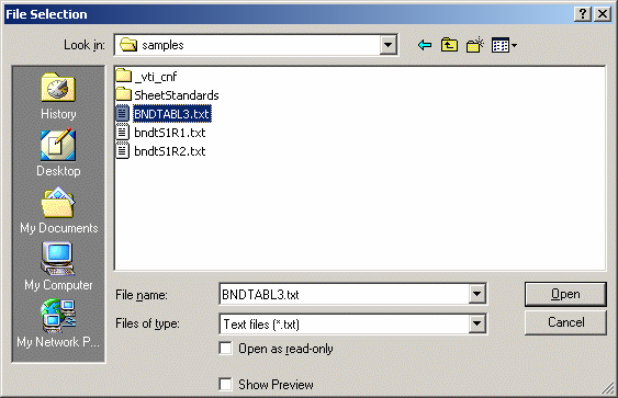
These files are available under .txt format or .xls format (only for Windows)
-
Click Open.
In the Sheet Metal Parameters dialog box, the Design Table icon
appears opposite the Thickness and Bend radius fields.
-
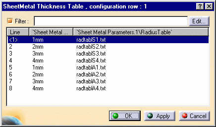
Click the Thickness Design Table icon
 and select the line containing the appropriate parameters (for example
Line 1).
Using the Tools -> Options -> General -> Document
tab, Other Folders option, you can specify where the files are
located. Refer to
Document.
This scenario can work when the .CATPart document and all reference table
files (Design & Radius) are located in the same directory. This directory is
the current one when the Design table is created, and also when the .CATPart
is open.
However, generally speaking, you must reference the complete path
indicating where the radius table files are to be found in the RadiusTable
column. In this case, regardless of the current directory, the correct
tables are located when re-opening the .CATPart document.
-
Click OK.
The parameter values are updated in the Sheet Metal Parameters dialog box.
-
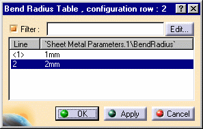
Click the Bend Radius Design Table icon
 .
. -
Select line 2 and click OK. The parameter values are updated in the Sheet Metal Parameters dialog box.
-
Create a flange.
The Flange definition dialog box reflects the modification for the Radius.
The default mode, that is to say the formula:
Bend Radius = Part Radius is deactivated.
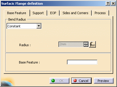
Using the Sheet Metal Design Tables:
-
Click the Design Table icon
 and select a line.
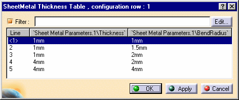
-
Click OK.
The parameter values are updated in the Sheet Metal Parameters dialog box.
At that time, the parameters Thickness and Bend radius are
driven by the design table.
They are now in gray, indicating that you can no longer modify the values.
Note that if you create a bend, there is no design table: it's the formula
which is used.
To disable the access to design tables:
-
Select the Tools -> Options -> Part -> Display tab and check Relations: the Design Table icon
 is displayed in the specification tree.
 -
Right-click this icon: the contextual menu appears.
-
Select SheetMetal Thickness Table object -> Deactivate
The relation is no longer used but still exists. It can be activated at any time.
![]()