The Structure Drawing tab contains the following categories of options:
|
|
Molded forms
|
|
LinetypeDefines the linetype used to represent molded forms on drawings. Select the desired linetype from the dropdown list.
|
|
Apply linetype on profile view onlyIf this check box is selected, the selected linetype is applied to profile views only.
|
|
Members / Stiffeners
|
|
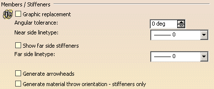
Graphic replacementIf this check box is selected, a line representing the trace of visible members / stiffeners is generated on drawings. The user can specify the linetype (near side linetype) for this line.
|
|
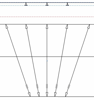
Anglular toleranceDefines the value above which the member/ stiffener section is not represented. It is the angle between the member/ stiffener section and the projection vector. In the example below, the angular tolerance is 15. |
|
 |
|
Near side linetypeDefines the linetype to be used for the trace of visible members / stiffeners if the Graphic replacement option is selected. Select the desired linetype from the drop-down list. A solid line font is recommended. |
|
Show far side stiffenersIf this check box is selected, a line representing the trace of hidden members / stiffeners, below a deck for example, is generated on drawings. The user can specify the linetype (far side linetype) for this line.
|
|
Far side linetypeDefines the linetype to be used for the trace of hidden members / stiffeners if the Show far side stiffeners option is selected. Select the desired linetype from the drop-down list. A phantom font is recommended. |
|
Generate arrowheadsIf this check box is selected, arrows are generated at ends of members / stiffeners.
|
|
Generate material throw orientation - stiffeners onlyIf this check boxis selected, marks indicating the material throw
orientation of stiffeners are generated.
Note: This option is valid for stiffeners only.
|
|
Plates
|
|
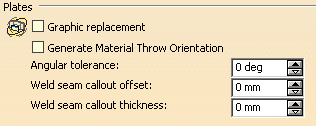
Graphic replacementIf this check box is selected, you can define how plates will be represented on drawings.
|
|
Generate Material Throw OrientationIf this check box is selected, marks indicating the material throw orientation of plates are shown on drawings.
|
|
Angular toleranceSpecifies an angular tolerance. If the angle between plates is less than the specified value, weld seams are generated; if the angle is greater than or equal to the specified value, knuckle lines are generated.
|
|
Weld seam callout offsetSpecifies the offset for weld seam callouts.
|
|
Weld seam callout thicknessSpecifies the thickness for weld seam callouts.
|
|
Openings
|
|
Graphic replacementIf this check box is selected, the user can define the symbols to use to represent openings on drawings.
|
|
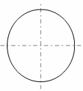
Center line representationDefines the symbol used for the centerline on front views if the Graphic replacement option is selected. Two options are available: |
|
|
|
|
|
|
Butterfly symbol thicknessDefines the thickness of the butterfly symbol in mm. Applies to profile views.
|
|
Midship Designation
|
|
Generate hull centerlineIf this check box is selected, the hull centerline is generated on drawings.
|
|
Hull centerline textDefines the text to be placed at both ends of the centerline.
|
|
Symbol representationIf this check box is selected, the midship symbol is generated on drawings. Note that dimensions of this symbol do not change.
|
|
Datum Line
|
|
Generate datum lineIf this check box is selected, a datum line is generated on drawings.
|
|
Annotation styleDefines the annotation style to use for the datum line. Options available are:
|
|


