|
|
This task illustrates how to create a
Multi-Axis Flank Contouring operation when the drive surfaces are non
contiguous. In this scenario, you will use:
|
|
|
|
Open the
AMG2Solids.CATProduct
document, then select Machining > Advanced Machining from
the Start menu. Make the Manufacturing Program current in the
specification tree. |
|
|
|
1. | Select the Multi-Axis Flank Contouring icon
|
| 2. | Use the sensitive icon in the Geometry page
|
|
|
|
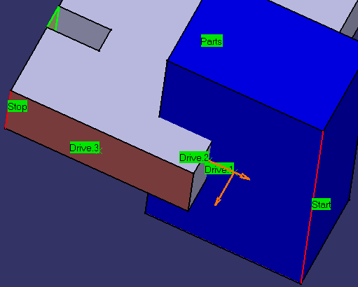
Drives 1 and 2 are non contiguous: they
belong to different solids. Stopping and Restarting conditions must be defined on non contiguous drives. |
|
|
|
||
| Arrows appear on Drives 1 and 2 indicating
the orientation for each contiguous section. Make sure that they are
oriented outward.
Arrows appear whenever necessary to indicate the orientation for your drive selection. You must make sure that they are correctly oriented. |
||
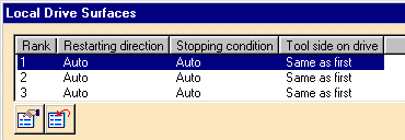
| 3. | Right click the drive surfaces area in the sensitive icon of the
Geometry page and select
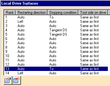
Local Modifications. The Local Drive Surfaces dialog box
appears.
|
|
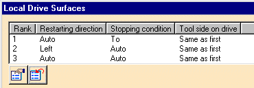
| 4. | Double click line 1, which corresponds to the first drive. The Local
Drive Surface 1 dialog box appears. Set the Stopping condition to
To.
Access the Local Drive Surface 2 dialog box using the '>>' button and set Restarting direction to Left. |
|
| 5. |
The Local Drive Surfaces dialog box is updated as follows:
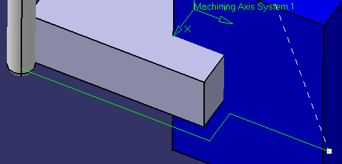
Check the validity of the operation by replaying the tool path.
|
|
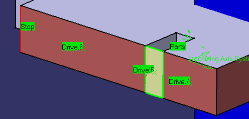
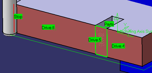
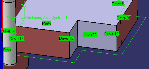
| 6. | Change the position of the Stop element, then select Drives 4, 5 and
6.
These Drives are non contiguous: Drive 5 is in fact geometry added by the user to close the gap between Drives 5 and 6.
|
|
| 7. | Access the Local Drive Surface 4 dialog box and set Stopping
condition to Tangent DS. Access the Local Drive Surface 5 dialog box and set Stopping condition to Tangent DS. Check the validity of the operation by replaying the tool path.
|
|
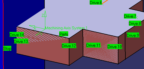
| 8. | Change the position of the Stop element, then select Drives 7
to 13 on the flanks of the gray solid. Select the last Drive 14 on the
flank of the blue solid.
Drives 13 and 14 are non contiguous: they belong to different solids. An arrow appears on Drive 6 indicating the orientation for the contiguous section. Make sure that it is oriented outward.
|
|
| 9. | Access the Local Drive Surface 13 dialog box and set Stopping
condition to To. Access the Local Drive Surface 14 dialog box and set Restarting direction to Left. |
|
|
|
||
| Check the validity of the operation by
replaying the tool path.
|
||
| 10. | Click OK to create the operation. | |
|
|
Right clicking in the Local Drive Surfaces
dialog box gives access to a number of contextual commands:
|
|
|
|
||
