 |
-
Click Check
 in the Analysis toolbar.
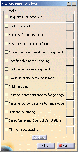
| The BiW Fasteners Analysis dialog box opens. |
 |
-
Check the rules on which you want to run the analysis.
-
Uniqueness of identifiers: checks that
all joint elements have different names.
- Thickness count: checks that the number of
thicknesses is compliant with the number set in the BiW
parameters.
- Forecast fasteners count: checks that the number
of joint elements the joint body is supposed to contain for
further verifications is compliant with the number set when
creating the joint and the joint body.
- Fastener location on surface: checks that joint
elements are located on surfaces.
 |
This rule applies for spot
points only. |
- Closest surface normal vector alignment:
checks that the fastener's normal vector is parallel to the
computed normal at the projection point on the closest surface.
- Specified thicknesses crossing:
checks that joint elements cross all the specified thicknesses of
the joint body.
- Thicknesses normals alignment: checks that the
thickness normal to the crossed joined components is aligned with
the joint element's normal.
- Maximum/Minimum thickness ratio: checks that the
ratio between the minimum and the maximum thicknesses of the
crossed zones is lower or equal to the maximum defined ratio,
even if all joint elements do not intersect all the specified
joined components.
 |
- In case the maximum ratio is set to 1, the rule checks
that all crossed thicknesses are equal.
- If one or more thicknesses are null, the ratio is
infinite.
- For curve beads, specified crossed thicknesses are
computed at the start location.
|
-
Thickness gap: checks that the gap
value between two joined components crossed by a given joint
element is compliant with the value set in the BiW parameters.
- Fastener center distance to flange edge: checks
that all joint elements on crossed surfaces intersect all
specified components and computes the minimum distance from the
fastener's center location to the closest flange edge.
- Fastener border distance to flange edge: checks
that all joint elements on crossed surfaces intersect all
specified components and computes the minimum distance from the
fastener's border location to the closest flange edge.
- Diameter overhang: checks the maximum overhang of
the fastener's diameter to the closest flange edge.
 |
- The above three rules apply for spot points and spot
projection welds only, not curve beads.
- In case two or more surfaces with common edges are
crossed, you need to perform a join so their free edges are
considered as those of one single surface.
- Internal edges and tangent surfaces are ignored, but
holes are not.
- For rivets, the diameter taken into account is the
shank diameter.
|
- Series Name and Count of
Annotations: checks that the name of the series (Joint
Name, Joint Body Name, etc.) and the number of annotations
is compliant with the value set in the BiW parameters.
- Minimum spot spacing: checks that the minimum spot
spacing between two spot points is compliant with the value set
in the BiW parameters.
 |
This rule applies for spot
points only. |
|
-
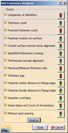
Click Analyze.
| Besides each rule, a sign gives a feedback whether the check
passed or failed. |
| All failing elements are selected and highlighted in the 3D
geometry for a further check that will only take into account the
current selection. |
 |
-
Click the red sign corresponding to the
rule that failed. The corresponding check failure analysis window
opens, along with the list of selected failing elements. You can select
several elements in the list to highlight them in the specification
tree and 3D geometry.
- The Closest surface normal vector alignment check failure
report displays either "N/A" when no normal vector was found on
the joint element (which is the case when you open a pre-V5R12
model) or the deviation angle between the normal vector of the
joint element and the normal vector at the projection on the
closest surface. You can then select the Joint Elements you want
to "heal" and either with the "Apply remedial action" contextual
menu or push button, reset the normal vector according to the
normal vector at the projection on the closest surface.
- The Fastener location on surface check failure report
displays either "N/A" if the joint element cannot be projected on
any surface or the distance to the closest surface. Same as
before, applying the Remedial action on a joint element will
project it on the closest surface.
- The Fastener center distance to flange edge, Fastener border
distance to flange edge, or Diameter overhang ratio check failure
report displays either "N/A" when no free edge can be found on
any crossed surface or the distance of the failed joint elements.
It highlights the closest edges involving the failure in the 3D
geometry, for instance when a fastener is equidistant between
several edges (see picture below).
- The Series Name and Count of Annotations check failure report
displays the erroneous fastener and the attached annotation when,
for instance, a joint element has been deleted in the joint body
or the joint body has been renamed. Applying the Remedial action
on a joint element modifies and automatically updates the
annotation.
|
|