[ Previous |
Next |
Contents |
Home |
Search ]
AIX Version 4.3 Kernel and Subsystems Technical Reference, Volume 2
Serial DASD Fence Command
The Serial Direct Acess Storage Device (DASD) controller
supports up to eight hosts and can fence, or lock out, specified hosts. Fences are
established and removed via the Serial DASD subsystem Fence command. Once a fence is
established, it can only be removed with another Fence command or by cycling the power to
the controller.
Hardware Implementation
Each DASD has an associated two-byte fence register
in the controller. A bit set to 1 indicates the host attached to the specified host
connector on the back of the controller drawer can only issue the Inquiry, Request Sense,
Fence, and Read(10) Serial DASD subsystem commands. The read with reservation (RWR) bit
must be set in the command descriptor block. The host connectors on the back of the
controller drawer are labeled from 0-7, and the fence register bits are ordered from left
to right. The host connector bit is 0.
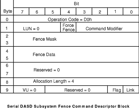
The following diagram illustrates the
Serial DASD Fence command descriptor block:
The command descriptor block for the Fence command
contains the following fields:
| Operation Code
|
Specifies the operation code for this command. The value of this field is
always D0h. |
| LUN |
Logical unit number. The value of this field is always 000. |
| Force Fence |
Specifies how to run the Fence command. It can have the following values:
| 0 |
Runs the Fence command from a host that is not fenced-out. |
| 1 |
Runs the Fence command from a fenced-out host. |
|
| Command Modifier
|
Specifies which type of fencing operations is to be used. The command modifier
can have one of the following values:
| 0001 |
Indicates the Mask and Swap operation performs the following equation in order
to set the DASD's fence bit register:
(fence data field & fence mask field) | (old fence
register value & ~fence mask field)
That is, the fence mask field specifies which bits in the
fence data field should be used.
The Mask and Swap operation allows fences for multiple
hosts to complement one another, since they do not need to know the current state of the
fence to fence out another host. For example, if host0 and host3 are currently fenced
out, then the fence register will have the value of 1001000000000000. To unfence host3
using Mask and Swap requires the fence data field to be set to 0000000000000000 and the
fence mask field to be set to 0001000000000000. |
| 0010 |
Indicates the Compare and Swap fencing operation sets the DASD's fence bit
register, depending on the value of the fence mask field. If the old fence bit register
equals fence mask field, the fence bit register is set equal to the fence data field.
Otherwise, the fence bit register remains unchanged. |
|
| Fence mask |
Indicates a 16-bit fence mask field. Its value is dependent on the value of
the Command Modifier component. |
| Fence data |
Indicates a 16-bit fence data field. Its value is dependent on the value of
the Command Modifier component. |
| Reserved |
The value of this field is always 0000000000000000. |
| Allocation Length |
The value of this field is always 00000100. |
| VU |
The value of this field is always 00. |
| Reserved |
The value of this field is always 0000. |
| Flag |
The value of this field is always 0. |
| Link |
The value of this field is always 0. |
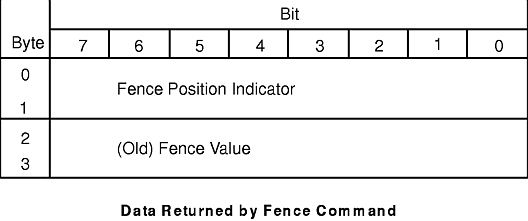
The Fence command also supplies a method to determine
which hosts are currently fenced out as well as which tail the current host is connected
via the data returned from the Fence command. The following diagram illustrates the data returned
by the
Fence command.
A fence cannot be removed by a reset. It can only be
removed by cycling power on the controller of the DASD, or by issuing a Fence command.
Software Implementation
The Serial DASD subsystem device driver uses the
hardware's Mask and Swap fence commands to set and remove fences. The device driver also
uses the Mask and Swap fence command with the fence mask set to all zeroes to determine
its current host position.
The Serial DASD controller configuration method enables
the fencing mechanism. Once enabled, a user can create or remove fences with ioctls to
individual DASDs. The device driver maintains a fence by reestablishing it whenever the
DASD is powered off and on.
Related Information
Serial DASD Subsystem Device
Driver.
Serial DASD Concurrent Mode of
Operation Interface.
Device-Dependent Subroutines for
Serial DASD Operations.
Device-Dependent Subroutines for
Serial DASD Adapter Operations.
Device-Dependent Subroutines for
Serial DASD Controller Operations.
Direct Access Storage
Device (DASD)
Overview in AIX Version 4.3 Kernel Extensions and Device Support Programming Concepts.
[ Previous |
Next |
Contents |
Home |
Search ]