Modems provide serial communications across ordinary telephone lines. This section discusses modem standards, general modem setup, and specific configuration tips for popular modems.
A modem is a device that allows you to connect one computer to another across ordinary telephone lines. The current telephone system is incapable of carrying the voltage changes required for a direct digital connection. A modem overcomes this limitation by modulating digital information into audio tones for transmission across the phone line, and by demodulating those tones back into digital information on reception. Modems are commonly used with Basic Network Utilities (BNU) or other implementations of the UNIX-to-UNIX Copy Program (UUCP). A high-speed (14,400 bps or greater) modem can be used with Serial Line Interface Protocol (SLIP) to provide Transmission Control Protocol/Internet Protocol (TCP/IP) connectivity as well.
Often, the term baud is used to refer to a modem's speed instead of bps. Baud is actually a measurement of the modulation rate. In older modems, only 1 bit was encoded in each signal change, so a modem's baud rate was equal to the modem's speed. Modems that operate at higher speeds, however, still generally operate at 2400 (or even 1200) baud, and encode two or more bits per signal change. A modem's bps rate is calculated by multiplying the number of data bits per signal with the baud (for example, 2400 baud x 6 bits per signal change = 14,400 bits per second). Most modern modems can communicate at a variety of speeds (for example, 14,400, 9600, 7800, 4800, and 2400 bps).
The older speeds of 300, 1200, and 2400 bps were well defined. However, as modem manufacturers began to devise methods for gaining higher speeds, each modem manufacturer started to use a proprietary method incompatible with modems from other manufacturers. Today, the ITU-TSS (formerly the United Nations Consultative Committee for International Telephony and Telegraphy, abbreviated CCITT) defines standards for most high-speed communications.
Even high-speed modems are much slower than other methods of computer communication. A high-speed modem may operate at 28,800 bps, but an Ethernet connection operates at 10,000,000 bps. In order to boost data throughput, high-speed modems typically offer one or more data compression algorithms. These algorithms can boost the throughput of a high-speed modem to speeds of 57,600 bps (if the data rate is 14,400 bps) or 115,200 bps (if the data rate is 28,800 bps). Note that these compression algorithms are sensitive to the data being transmitted. If the data has already been compressed (for example, with the compress command), the data compression methods of high-speed modems will offer little or no benefit, and might even reduce data throughput. When using a modem with data compression technology, the speed of the data terminal equipment/data circuit-terminating equipment (DTE/DCE) connection between the computer and the modem should be greater than the nominal data rate of the connection between modems, and equal . For example, with a V.32bis modem with V.42bis data compression, the data rate of the modem (the speed at which the modem communicates across telephone lines) is 14,400 bps. When the V.42bis compression is active, actual data throughput can reach 57,600 bps. To accommodate the greater throughput offered by data compression, the speed of the DTE/DCE between the computer and the modem should be set to 57,600 bps.
Attention: Some modems implementing data compression and modern modulation schemes may yield a higher data throughput than some systems and asynchronous adapters can accommodate.
Today, the ITU-TSS (formerly, the CCITT) defines standards for high-speed communications, including data compression algorithms. ITU-TSS standards are usually named V.nn, where nn is a number. Another, slightly less common standard is the Microcom Networking Protocol (MNP). Available in versions (called classes) 1-9, MNP is a high-performance, high-speed protocol that was available relatively early, and became something of a de facto standard before the advent of the CCITT standards.
Following is a list of some common communications standards defined by the ITU-TSS. Note that this only a partial list.
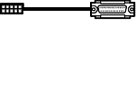
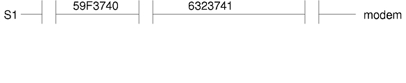
The first step in setting up a modem is to attach the modem with the appropriate cables. Part numbers and their descriptions are listed below.
| 6323741 | Async Cable, EIA-232; used to attach all asyncronous devices; sometimes used with other cable assemblies. |
| 59F3740 | 10 to 25-pin D-shell connector used to attach asyncronous cable 6323741 to native serial ports S1 and S2
as shown in the following figure.
|
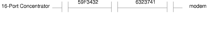
| 59F3432 | Cable P used to connect to 16-port concentrator. Part number includes four RJ45-to-DB25 converter cables. |
Following are some examples of cable connections:

First, ensure that the system is turned on and that the modem is turned off. Use the Web-based System Manager fast path, wsm devices, or the SMIT fast path smit mktty. Example port settings for the tty are given below:
Note that the port number, the baud rate, and the enabling of login depend on your setup:
The Enable LOGIN parameter can have the following settings:
Two methods for configuring the modem are presented in this section. You only need to use one method.
If you have the Basic Network Utilities (BNU) installed, you can use the cu command to configure a modem as follows:
Direct tty# - Any direct
Note: You need issue only one of the following commands.
Note: Issue the following command only if the previous command caused the modem to disconnect.
penable  tty#
pshare   tty#
pdelay   tty#
pdisable tty#
The modem now has the basic configuration needed for most system communications. If you have problems, invoke cu with the cu -dl command to start a diagnostic trace on the connection.
If the previous method failed, or if you do not have BNU installed, try running the following C program. Create a file called motalk.c containing the following code. Save the file. Compile and run it according to the instructions in the program comments.
/*************************************************************/
/*  MoTalk - A "C" program for modem setup.                */
/*           This program is meant as an aid only and is   */
/*           not supported by IBM.                       */
/*                  compile:  cc -o motalk motalk.c       */
/*                  Usage:  motalk /dev/tty? [speed]      */
/*************************************************************/
#include <errno.h>
#include <stdio.h>
#include <signal.h>
#include <fcntl.h>
#include <termio.h>
FILE *fdr, *fdw;
int fd;
struct termio term_save, stdin_save;
void Exit(int sig)
{
   if (fdr) fclose(fdr);
   if (fdw) fclose(fdw);
   ioctl(fd, TCSETA, &term_save);
   close(fd);
   ioctl(fileno(stdin), TCSETA, &stdin_save);
   exit(sig);
}
main(int argc, char *argv[])
{
   char *b, buffer[80];
   int baud=0, num;
   struct termio term, tstdin;
   if (argc < 2 || !strcmp(argv[1], "-?"))
   {
      fprintf(stderr, "Usage: motalk /dev/tty? [speed]\n");
      exit(1);
   }
   if ((fd = open(argv[1], O_RDWR | O_NDELAY)) < 0)
   {
      perror(argv[1]);
      exit(errno);
   }
   if (argc > 2)
   {
      switch(atoi(argv[2]))
      {
         case   300: baud = B300;
                     break;
         case  1200: baud = B1200;
                     break;
         case  2400: baud = B2400;
                     break;
         case  4800: baud = B4800;
                     break;
         case  9600: baud = B9600;
                     break;
         case 19200: baud = B19200;
                     break;
         case 38400: baud = B38400;
                     break;
         default:    baud = 0;
                     fprintf(stderr, "%s: %s is an unsupported baud\n", argv[0],argv[2]);
                     exit(1);
         }
      }
   /* Save stdin and tty state and trap some signals */
   ioctl(fd, TCGETA, &term_save);
   ioctl(fileno(stdin), TCGETA, &stdin_save);
   signal(SIGHUP, Exit);
   signal(SIGINT, Exit);
   signal(SIGQUIT, Exit);
   signal(SIGTERM, Exit);
   /*  Set stdin to raw mode, no echo */
   ioctl(fileno(stdin), TCGETA, &tstdin);
   tstdin.c_iflag = 0;
   tstdin.c_lflag &= ~(ICANON | ECHO);
   tstdin.c_cc[VMIN] = 0;
   tstdin.c_cc[VTIME] = 0;
   ioctl(fileno(stdin), TCSETA, &tstdin);
   /*  Set tty state */
   ioctl(fd, TCGETA, &term);
   term.c_cflag |= CLOCAL|HUPCL;
   if (baud > 0)
   {
      term.c_cflag &= ~CBAUD
      term.c_cflag |= baud;
   }
   term.c_lflag &= ~(ICANON | ECHO); /* to force raw mode */
   term.c_iflag &= ~ICRNL; /* to avoid non-needed blank lines */
   term.c_cc[VMIN] = 0;
   term.c_cc[VTIME] = 10;
   ioctl(fd, TCSETA, &term);
   fcntl(fd, F_SETFL, fcntl(fd, F_GETFL, 0) & ~O_NDELAY);
   /*  Open tty for read and write */
   if ((fdr = fopen(argv[1], "r")) == NULL )
   {
      perror(argv[1]);
      exit(errno);
   }
   if ((fdw = fopen(argv[1], "w")) == NULL )
   {
      perror(argv[1]);
      exit(errno);
   }
   /*  Talk to the modem */
   puts("Ready... ^C to exit");
   while (1)
   {
      if ((num = read(fileno(stdin), buffer, 80)) > 0)
         write(fileno(fdw), buffer, num);
      if ((num = read(fileno(fdr), buffer, 80)) > 0)
         write(fileno(stdout), buffer, num);
      Exit (0);
   }
}
Example settings for the modem follow. (tty0 is the tty for this example and the baud rate may be changed depending on your modem. Generally, you want to keep the baud rate at the highest speed that the modem can allow.)
STTY attributes for RUN TIME should be:
[hupcl,cread,brkint,icrnl,opost,tab3,onlcr,icanon,echo,echoe,echok,echoctl,
echoke,imaxbel,iexten]
(No ixon/ixoff needed)
STTY attributes for LOGIN should be:
[hupcl,cread,echoe,cs8](No ixon/ixoff needed)
hayes Nvr HAYESPROG 2400
# For programming the  hayes modem only:
HAYESPROG tty0 - 2400 HayesProgrm2400
#regular ACU entry:
ACU tty0 - Any hayes
# This Entry is used to PROGRAM the modem ONLY:
# the next 3 lines should be made into one:
HayesProgrm2400     =,-,     "" \d\dAT\r\c OK AT&F\r\c OK ATM1\r\c OK
AT&D3\r\c OK AT&K3&C1\r\c OK ATL0E0Q2\r\c OK ATS0=1\r\c OK AT&W\r\c
OK
hayes     =,-,     "" \dAT\r\c OK ATDT\T\d\r\c CONNECT
If you are not doing binary file transfers or using BNU, leave out the &K3 command, and set XON-XOFF handshaking to Yes in SMIT or checked in Web-based System Manager. However, it is more efficient to use hardware flow control (as opposed to XON-XOFF handshaking). To do that, use the settings and the Dialers entries from step 5.
After the modem is programmed, you must set request to send (RTS) line discipline to allow the system device driver to use hardware flow control. To do that, the modem must be connected to another system (to bring carrier high) and the following command must be run:
stty add rts < /dev/tty0
Be sure to substitute tty0 with your tty number. This works until the next reboot, when it must be done again. For the addition of RTS to be done automatically at system startup, type in and compile the addrts.c program that follows, and place a line in /etc/rc that calls the program on system startup. (This program does not require carrier to be high.) The command is:
addrts /dev/tty0
The full path to the command must be specified if the addrts program is not in one of the directories in the PATH. (Substitute your tty number for tty0 above.)
/*             C Program to add RTS discipline to tty port(s).

   Tips:
         To make the program more permanent, insert the file name of
         the compiled version (complete with path) at the end of your
         "/etc/rc" file and the changes will take effect again at next
         reboot.

         NOTE: This program is supplied "as is" and is NOT supported by
               IBM.  It is intended as an aid to administrators only.

 _________________________________________________________________
     To create:     vi addrts.c <enter>
     To compile:    cc -o addrts  addrts.c
     Usage is:      addrts /dev/tty##
 ________________________________________________________________ */
/*                         Program starts now                  */
#include <stdio.h>
#include <fcntl.h>
#include <termios.h>
#include <sys/tty.h> main (argc,argv)
{
   int argc;
   char *argv[];
   int fd;
   if ( (fd = open(argv[1], O_NDELAY|O_RDWR)) <0 )
   {
      printf("%s: could not open %s\n",argv[0],argv[1]);
      exit (22);
   }
   ioctl(fd, TXADDCD, "rts");
   /*  adds rts to the tty in the argument */
   close(fd);
}
Following are some specific configuration tips and setup information for a variety of popular modems.
Note: This guide uses tty0 as an example. Substitute the tty to which the modem is attached for tty0 .
To use the IBM 7855 modem as a dial-in or dial-out modem on the system, the modem must be set to accept AT commands. To do this, press the right and left arrow keys on the front of the modem at the same time. The front panel should then read:
<Exit Enter>
Press the right arrow to enter, and the down arrow until you see First Setup ; t hen the right arrow. Press the up arrow until you see Asynchronous AT. Press the left arrow until you exit out of the setup menu.
Note: Options that are not needed are not included in the following list.
STTY attributes for RUN TIME should be:
[hupcl,cread,brkint,icrnl,opost,tab3,onlcr,icanon,echo,echoe,echok, echoctl,echoke,imaxbel,iexten](No ixon/ixoff needed)
STTY attributes for LOGIN should be:
[hupcl,cread,echoe,cs8](No ixon/ixoff needed)
ibm7855 Nvr IBMPROG 19200
slip Nvr SLIPPROG 19200
IBMPROG tty0 - Any IBMProgrm
SLIPPROG tty0 - Any SlipProgrm

# Usual ACU entry
ACU tty0 - Any ibm

# ACU entry to quietly dial the modem.
ACUQ tty0 - Any ibmq

# IBM7855 ACU entry to negotiate for error correction and compression
ACUECLC tty0 - Any ibmeclc

# IBM7855 ACU entry to negotiate for error correction and compression
# using large (256 byte) data block size
ACUECLB tty0 - Any ibmeclclb

# IBM 7855 ACU entry to use ECL without compression
ACUECL tty0 - Any ibmecl
# IBM 7855 program. Use ibmeclcbc for 256 byte block size.  However,
# Noisey lines may obtain better throughput by setting the block size to
# be 64 bytes; compressed files will show better throughput by turning off
# compression.
# The following 3 lines should be joined into one line:
IBMProgrm       =,-,    "" \dATQ0\r\c OK AT&F\r\c OK ATM1\r\c OK
AT&D3\r\c OK AT&C1\R2\Q2\M14\r\c OK AT&B8N1L0E0\r\c OK ATS0=1\r\c
OK ATQ1&W0&Y0\r\c ""

# The following 3 lines should be joined into one line:
SlipProgrm      =,-,    "" \dATQ0\r\c OK AT&F\r\c OK ATM1\r\c OK
AT&D3\r\c OK AT&C0\R2\Q2\r\c OK AT&B8N1L0E0\r\c OK
ATS0=1\r\c OK ATQ1&W\r\c ""

ibm     =,-,    "" \dATQ0\r\c OK ATDT\T\d\r\c CONNECT
ibmq    =,-,    "" \dATQ0\r\c OK ATM0DT\T\d\r\c CONNECT

#IBM 7855 with ECLC and Compression
# (Note two backslashes are needed before the N; cu won't send \N
# without preceeding it with a \)
ibmeclc =,-,    "" \dAT\\N3%C1Q0\r\c OK ATDT\T\d\r\c CONNECT

#IBM 7855 ECLC Compression with 256 byte block size
ibmeclclb       =,-,    "" \dAT\\N3%C1Q0\A3\r\c OK ATDT\T\d\r\c CONNECT

# IBM 7855 ECL without compression
ibmecl  =,-,    "" \dAT\\N3%C0Q0\r\c OK ATDT\T\d\r\c CONNECT
The command fails because no one is connected, but if the following is in the output:
Sendthem (ATQ1&W0&Y0^MNO CR)
expect: ("")
got it
it is successfully programmed. The LED on the front should read ASYN8N A 9600 a . You can then pshare tty0 .
After the modem is programmed, you can set RTS line discipline to allow hardware flow control. To do that, the modem must be connected to another system (to bring carrier high) and the following command must be run:
stty add rts < /dev/tty0
Be sure to substitute tty0 with your tty number. This will be good until the next system startup, then it will need to be done again.
Alternatively, you could type in and compile the addrts.c program, listed below, and place a line in /etc/rc that will call the program on system startup to add RTS to the line. This program does not require carrier to be high.
/*             C Program to add RTS discipline to tty port(s).

     Tips:
          To make the program more permanent, insert the file name of
          the compiled version (complete with path) at the end of your
          "/etc/rc" file and the changes will take effect again at next
          reboot.  Usage is addrts /dev/tty##.


          NOTE: This program is supplied "as is" and is NOT supported by
                IBM.  It is intended as an aid to administrators only.
 _______________________________________________________________________
     To create:     vi addrts.c <enter>
     To compile:    cc -o addrts  addrts.c
 _______________________________________________________________________ */
/*                         Program starts now                  */
#include <stdio.h>
#include <fcntl.h>
#include <termios.h>
#include <sys/tty.h>
main (argc,argv)
        int argc;
        char *argv[];
{
        int fd;
        if ( (fd = open(argv[1], O_NDELAY|O_RDWR)) <0 ) {
                printf("%s: could not open %s\n",argv[0],argv[1]);
                exit (22);
                }
        ioctl(fd, TXADDCD, "rts");  /*  adds rts to the tty in the argument */
        close(fd);
}
ATL5
B1 E1 M1 Q0 R0 V1 X0 &E1 &E4 &E6 &E8 &E10 &E13 &E15
$MB9600 $SB9600 $BA0 &W0

OK
ATL6
S0   S2   S3   S4   S5   S6   S7   S8   S9   S10  S11  S13  S24  S25  S30
001  043  013  010  008  002  045  002  025  007  070  037  020  001  000

OK
ATL7
$A0 &A0 #A0 &B0 &BS1 &C1 $D0 &D2 #DB0 $EB0 %E1 #F0 $F1 &G0 #L0 $MI0 &M0
&P0 #P2 &Q0 $R0 &R1 &RF1 &S0 $SP0 &SF0 #T1 $V0 $V6 $VD0 &X0 Y0
$MB9600 $SB9600 $BA0 &W0
OK
Note: In the example above, the s9 register has been set to 25. The default is 6. The normal setting should be between 15 and 20.
/*  C Program to add RTS discipline to tty port(s).

  NOTE: This program is supplied "as is" and is NOT supported by
        IBM.  It is intended as an aid to administrators only.    */
/*                         Program starts now                    */
#include <stdio.h>
#include <fcntl.h>
#include <termios.h>
#include <sys/tty.h>
main()
{
   int fd;
      fd = open("/dev/tty0", O_NDELAY|O_RDWR);
      ioctl(fd, TXADDCD, "rts");      /*  adds rts to tty0       */
      close(fd);
}
/* END Program */Note: Options that are not necessary are not included in the following list.
[hupcl,cread,brkint,icrnl,opost,tab3,onlcr,icanon,echo,echoe,echok,
echoctl,echoke,imaxbel,iexten]
(No ixon/ixoff needed)
STTY attributes for LOGIN should be:
[hupcl,cread,echoe,cs8](No ixon/ixoff needed)
pracper Nvr PRACPERPROG 2400
# For programming the Practical Peripherals modem only:
PRACPERPROG tty1 - 2400 PracPerProgram2400

# regular ACU entry:
ACU tty1 - Any hayes
# This Entry is used to PROGRAM the modem ONLY:
# the next 3 lines should be made into one:
PracPerProgram2400      =,-,    "" \d\dAT\r\c OK AT&F\r\c OK ATM1\r\c OK
AT&D3\r\c OK AT&C1\r\c OK ATL0E0\r\c OK ATS0=1S9=20\r\c OK AT&W\r\c
OK

hayes   =,-,    "" \dAT\r\c OK ATDT\T\d\r\c CONNECT
After the modem is programmed, you can set RTS line discipline to allow hardware flow control. To do that, the modem must be connected to another system (to bring carrier high) and the command stty add rts < /dev/tty0 must be run. (Be sure to substitute tty0 with your tty number). This works until the next system restart, when it must be done again. Alternately, type in and compile the addrts.c program, and place a line in /etc/rc that calls the program on system startup. This program does not require carrier to be high.
telebit Nvr TELEPROG 19200
#
#  Devices entry to use to program the T1600
#
TELEPROG tty0 - 19200 TelebitProgram
#
#  19200, 9600 baud (fast) Telebit Trailblazer modem
#
ACU       tty0 - 19200 tbfast \D
ACUTB     tty0 - 19200 tbfast \D
ACU96     tty0 - 9600 tbfast \D
#
#  2400 baud Telebit Trailblazer modem
#
ACU       tty0 - 2400 tb2400 \D
ACU24     tty0 - 2400 tb2400 \D
#
#  1200 baud Telebit Trailblazer modem
#
ACU       tty0 - 1200 tb1200 \D
ACU12     tty0 - 1200 tb1200 \D
#
# Entry to program the modem ONLY
# The next 3 lines should be made into one long line:
TelebitProgram  =,-,    "" \dAT&F\r\c OK
ats0=1s2=255s7=60s11=50s41=2s45=255s51=252s63=1s58=2s64=1\r\c OK
ATs69=2s105=0s111=30s255=0M0&C1Q2&D3&Q0&R3&S1&T5\r\c OK ATE0X12&W\r\c OK
#
# Telebit T1600 Dialers entries
#
tbfast  =,-,    "" \dATs50=255s7=60\r\c OK\r ATDT\T\r\c CONNECT-\d\c-CONNECT
tb2400  =,-,    "" \dATs50=3\r\c OK\r ATDT\T\r\c CONNECT
tb1200  =,-,    "" \dATs50=2\r\c OK\r ATDT\T\r\c CONNECT
telebit Nvr TELEPROG 19200
#
#  Devices entry to use to program the T2000
#
TELEPROG tty0 - 19200 TelebitProgram
#
#  19200, 9600 baud (fast) Telebit Trailblazer modem
#
ACU       tty0 - 19200 tbfast \D
ACUTB     tty0 - 19200 tbfast \D
ACU96     tty0 - 9600 tbfast \D
#
#  2400 baud Telebit Trailblazer modem
#
ACU       tty0 - 2400 tb2400 \D
ACU24     tty0 - 2400 tb2400 \D
#
#  1200 baud Telebit Trailblazer modem
#
ACU       tty0 - 1200 tb1200 \D
ACU12     tty0 - 1200 tb1200 \D
#
#  For sites with MNP modems
#
ACUM12     tty0 - 1200 tb12mnp \D
ACUM24     tty0 - 2400 tb24mnp \D
#
# Entry to program the modem ONLY
#
# The next 4 lines will be made into one:
TelebitProgram  =,-,    "" \dAT&F\r\c OK
ats2=255s7=60s11=50s41=2s45=255s51=252s52=2s54=3s58=2s64=1\r\c OK
ATs69=1s92=1s96=0s105=0s110=1s111=30s130=3s131=1F1M0Q6TV1W0X3Y0&P0&T5\r\c
OK ATE0&W\r\c OK  00
#
# Telebit T2000 dialers Entries:
#
tbfast  =,-,    "" \dATs50=255s7=60\r\c OK\r ATDT\T\r\c CONNECT-\d\c-CONNECT
tb2400  =,-,    "" \dATs50=3\r\c OK\r ATDT\T\r\c CONNECT
tb1200  =,-,    "" \dATs50=2\r\c OK\r ATDT\T\r\c CONNECT
tb24mnp =,-,    "" \dAT\r\c OK ATS0=0S95=2S50=3S41=0\r\c OK ATDT\T\r\c CONNECT
tb12mnp =,-,    "" \dAT\r\c OK ATS0=0S95=2S50=2S41=0\r\c OK ATDT\T\r\c CONNECT
telebit Nvr TELEPROG 19200
#
#  Devices entry to use to program the T3000
#
TELEPROG tty1 - 19200 TelebitProgram
#
#  19200, 9600 baud (fast) Telebit Trailblazer modem
#
ACU       tty1 - 19200 tbfast \D
ACUTB     tty1 - 19200 tbfast \D
ACU96     tty1 - 9600 tbfast \D
#
#  2400 baud Telebit Trailblazer modem
#
ACU       tty1 - 2400 tb2400 \D
ACU24     tty1 - 2400 tb2400 \D
#
#  1200 baud Telebit Trailblazer modem
#
ACU       tty1 - 1200 tb1200 \D
ACU12     tty1 - 1200 tb1200 \D
#
#  For sites with MNP modems
#
ACUM12     tty1 - 1200 tb12mnp \D
ACUM24     tty1 - 2400 tb24mnp \D
#
# Entry to program the modem ONLY
# The following 4 lines should be made into one long line:
TelebitProgram  =,-,    "" \dAT&F\r\c OK
ats0=1s2=255s7=60s11=50s41=2s45=255s51=252s63=1s58=2s64=1\r\c OK
ATs69=2s105=0s111=30s255=0M0&C1Q2&D3&Q0&R3&S1&T5\r\c OK ATE0X12&W\r\c
OK  00
#
# Telebit T2000 dialers Entries:  The tbfast won't work for the T3000,
# but the rest should.
#
tbfast  =,-,    "" \dATs50=255s7=60\r\c OK\r ATDT\T\r\c CONNECT-\d\c-CONNECT
tb2400  =,-,    "" \dATs50=3\r\c OK\r ATDT\T\r\c CONNECT
tb1200  =,-,    "" \dATs50=2\r\c OK\r ATDT\T\r\c CONNECT
tb24mnp =,-,    "" \dAT\r\c OK ATS0=0S95=2S50=3S41=0\r\c OK ATDT\T\r\c CONNECT
tb12mnp =,-,    "" \dAT\r\c OK ATS0=0S95=2S50=2S41=0\r\c OK ATDT\T\r\c CONNECT
Note: Options that are not necessary are not included.
[hupcl,cread,brkint,icrrnl,opost,tab3,onlcr,icanon,echo,echoe,echok, echoctl,
echoke,imaxbel,iexten]
(No ixon/ixoff needed)
STTY attributes for LOGIN should be:
[hupcl,cread,echoe,cs8](No ixon/ixoff needed)
uds Nvr UDSPROG Any
------------begin text to insert--------
# For programming the UDS modem only:
UDSPROG tty0 - 9600 udsmodemPROGRAM

# regular ACU entry:
ACU tty0 - Any uds
-------------end text to insert---------

**  Add this to /usr/lib/uucp/Dialers file:  **

------------begin text to insert--------
# the next 2 lines should be made into one:
udsmodemPROGRAM =,-,    "" \dAT&FQ2\r\c OK ATE0Y0&C1&D2&S1%B5%E0*LC\r\c
OK AT&W\r\c OK

uds    =,-,    "" \dAT\r\c OK\r ATDT\T\d\r\c CONNECT
When using the T3000 modem on a 128-port concentrator (operating at AIX level 3.2.3 Extended), change the tty settings using the Web-based System Manager fast path, wsm devices, or the SMIT fast path, smit chtty and change the following settings, both in the user interface and on the modem. Please do not use the 38400 baud rate shown below unless your serial hardware can support this speed. Make changes to baud speeds accordingly.
Example settings follow (only entries that must be changed are shown):
| TERMINAL type: | dumb |
| Enable LOGIN | share |
| BAUD rate | 38400 (may be 19200, or slower) |
| PARITY | none |
| BITS per character | 8 |
| XON-XOFF handshaking | no (at 9600 baud and over user RTS/CTS) |
tty settings for modem on 128-port adapter:
| Force Carrier: | disable |
| Perform Cooked Processing in Adapter: | disable |
| User Alternate RJ-45 Pinouts: | disable |
Suggested settings for modem registers and commands:
Notes:
This section attempts to identify common problems when using a modem with your computer.
| Symptom | Cause | Solution |
| The modem (or other device attached to the serial port) causes the system to gradually slow down and eventually hang. Turning off the device usually lets the system function normally again. | An intelligent modem has CD always ON. The system senses this and sends a login herald, which the modem tries to interpret as a command. The modem fails to recognize the login herald as a valid command, and echoes back to the tty port on the system. This cycle repeats continuously. | Set the tty port to delay on the system so no login herald will be sent. With this setting, only a valid carriage return character from the host logging in will cause a login herald to be sent. You can also change the modem's AT set profile to set CD to ON only when a valid carrier is sensed on the telephone line. |
Before calling for assistance with modem problems, please collect the following information:
The following is a summary of the Hayes Smartmodem command set. These commands comprise the AT command set used by many popular modems. This information comes from the Hayes Smartmodem 2400 Quick Reference Card, published by Hayes Microcomputer Products, Inc.
| Register | Range | Description |
| S0 | 0-255 | Select number of rings before answer. |
| S1 | 0-255 | Ring count (incremented with each ring). |
| S2 | 0-127 | Define escape sequence character (ASCII). |
| S3 | 0-127 | Define carriage return character (ASCII). |
| S4 | 0-127 | Define line feed character (ASCII). |
| S5 | 0-32, 127 | Define backspace character (ASCII). |
| S6 | 2-255 | Select wait-time in seconds before blind dialing. |
| S7 | 1-55 | Select wait-time in seconds for carrier/dial tone. |
| S8 | 0-255 | Select duration in seconds of comma. |
| S9 | 1-255 | Carrier detect response time in .1 second increments (10 = 1 second). |
| S10 | 1-255 | Delay between carrier loss and hangup in .1 second increments. |
| S11 | 50-255 | Duration/spacing of tones in milliseconds. |
| S12 | 50-255 | Escape sequence guard time in .02 second intervals. |
| S13 | -- | Reserved. |
| S14 | -- | Reserved. |
| S15 | -- | Reserved. |
| S16 | -- | Reserved - functions for this register are controlled by the &T commands). |
| S17 | -- | Reserved. |
| S18 | 0-255 | Test timer duration in seconds. |
| S19 | -- | Reserved. |
| S20 | -- | Reserved. |
| S21 | -- | Reserved. |
| S22 | -- | Reserved. |
| S23 | -- | Reserved. |
| S24 | -- | Reserved. |
| S25 | 0-255 | Select DTR change detect time in .01 second intervals. |
| S26 | 0-255 | RTS to CTS delay in .01 second intervals. |
| S27 | -- | Reserved. |
| Number | Word | Description |
| 0 | OK | Command executed. |
| 1 | CONNECT | Connection established at 0-300 bps. |
| 2 | RING | Ring signal detected. |
| 3 | NO CARRIER | Carrier signal lost or not detected. |
| 4 | ERROR | Invalid command, checksum, error in command line, or command line too long. |
| 5 | CONNECT 1200 | Connection established at 1200 bps. |
| 6 | NO DIALTONE | No dial tone detected. |
| 7 | BUSY | Busy signal detected. |
| 8 | NO ANSWER | No response when dialing a system. |
| 9 | CONNECT 2400 | Connection established at 2400 bps. |
The following lists and describes dial modifiers.