[ Previous |
Next |
Contents |
Home |
Search ]
AIX Versions 3.2 and 4 Asynchronous Communications Guide
Modem Considerations for AIX
The configuration of a modem attached to AIX is different than that of a personal computer (or PC). This section discusses modem interface requirements for the general user.
Section topics include the following:
- Supported Modems
- Data Carrier Detect Handling
- Data Terminal Equipment or Data Communication Equipment Speeds
- Modem Control Signals
Supported Modems
Any modem that is EIA 232 compliant, capable of returning results in response to a command, and capable of communication at one of the following baud rates can be attached to AIX:
 50 134  300 1800  9600
 75 150  600 2400 19200
110 200 1200 4800 38400
Data Carrier Detect Handling
The server uses the Data Carrier Detect (DCD) signal to monitor the true state of a modem. If the DCD signal on the modem's port is "high," the server believes the modem to be in use. It is therefore important to know which circumstances cause this signal to be forced into a "high" state. The DCD signal can be raised high for the following reasons:
- The use of clocal in the stty attributes for runtime field on the SMIT TTY Configuration panel.
- Having the Ignore Carrier Detect field set to enable on the SMIT TTY Configuration panel for ttys connected to a 128-port adapter.
- The modem forces DCD high with either AT commands or switches.
- The tty port is already in use by an application.
Note: When modems make a connection with another modem, the modem raises the CD. Most modem defaults settings set this signal "high" at all times even when the modem is idle. CD should not be forced "high."
Data Terminating Equipment or Data Circuit-Terminating Equipment Speeds
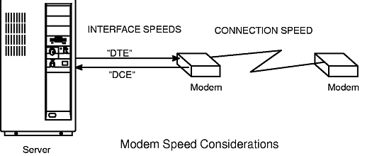
Data Terminating Equipment (DTE) and Data Communication Equipment (DCE) are used to describe two different hardware groups. The term DTE is used primarily for those devices that display user information. It also includes any devices that store or generate data for the user. The system units, terminals, and printers all fall into the DTE category.
DCE includes any device which can be used to gain access to a system over telecommunication lines. The most common forms of DCEs are modems and multiplexers.
With AIX serial communications involving modems, there are three major considerations:
- DTE interface speed (server to modem). This is the speed the server communicates to the modem.
- DCE interface speed (modem to server) sometimes called the "serial port interface speed." This is the speed at which the modem communicates to the server.
- Connection speed (modem to modem). This is the speed at which a modem communicates (or talks) to another modem. See illustration.
Most modern, high-speed modems allow the DCE interface speed to be different than the connection speed. This allows the DTE speed to be locked at a single baud rate while allowing the connection speed to fluctuate, up or down as needed, for proper communication between modems.
Modern high-speed modems hold the data to be transmitted to the server in a buffer and send it when the system can accept it. They can also hold data to be transmitted to the other modem in a buffer and send it as the remote is able to accept it. This kind of data transmission requires the modem and the server to engage in flow control.
Modem Control Signals
Modems are often used to initiate and receive calls. It is therefore important to program the modem to negotiate a connection at the highest possible speed and to reset itself to a known state after a connection is stopped. The server will toggle the Data Terminal Ready (DTR) signal from on to off to instruct the modem to terminate the connection. Most modems can be configured to reset themselves when this on-to-off DTR transition occurs.
Note: The tty can be configured to not drop DTR by unsetting the hupcl
flag in the stty run-time attributes.
For the connection between the server and the modem to be fully functional, the cabling must have the following qualifications:
- It must meet specifications.
- It should be properly shielded.
- The following signals should be provided: RxD, TxD, RTS, CTS, SG, DCD, and DTR.
Note: The 16-port asynchronous adapter does not provide support for the RTS and CTS signals. It is therefore impossible to use RTS/CTS hardware flow control with this adapter.
If binary data is to be transferred using a modem on this adapter, a file transfer protocol that detects incorrect data and resends the missing data (for example, Xmodem, zmodem, Kermit, and UUCP) should be used.
The following describes the signals used by the server:
| Signal |
Description |
|---|
| FG |
Frame Ground. Pin 1 of the EIA 232D specification that provides for a cable shield. Properly used, the signal is attached at pin 1 on one side of the cable only and is connected to a metal sheath around the cable. |
| TxD |
Transmit Data. Pin 2 of the EIA 232D specification. Data is transmitted on this signal. Controlled by the server. |
| RxD |
Receive Data. Pin 3 of the EIA 232D specification. Data is received on this signal, controlled by the modem, which is sent by the modem. |
| RTS |
Request To Send. Pin 4 of the EIA 232D specification. Used when RTS/CTS flow control is enabled. This signal is brought high when the system is ready to send data and dropped when the system wants the modem to stop sending data. |
| CTS |
Clear To Send. Pin 5 of the EIA 232D specification. Used when RTS/CTS flow control is enabled. This signal will be brought high when the modem is ready to send or receive data. It will be dropped when the modem wishes the server to stop sending data. Controlled by the modem. |
| DSR |
Data Set Ready. Pin 6 of the EIA 232D specification. Signals the server that the modem is in a state where it is ready for use. Controlled by the modem. |
| SG |
Signal Ground. Pin 7 of the EIA 232D specification. This signal provides a reference voltage for the other signals. |
| DCD |
Data Carrier Detect. Pin 8 of the EIA 232D specification. This provides a signal to the server that the modem is connected with another modem. When this signal is brought high, programs running on the server will be able to open the port. Controlled by the modem. |
| DTR |
Data Terminal Ready. Pin 20 of the EIA 232D specification. This provides a signal to the modem that the server is on and ready to accept a connection. This signal is dropped when the server wishes the modem to drop connection to another modem. It is brought high when the port is being opened. Controlled by the server. |
| RI |
Ring Indicate. Pin 22 of the EIA 232D specification. This provides a signal to the server that the modem is receiving a call. It is seldom used and is not needed for common operations. Controlled by the modem. |
[ Previous |
Next |
Contents |
Home |
Search ]