
|
95.023 bytes |
Service Hints & Tips |
Document ID: GCOR-38ZKYH |
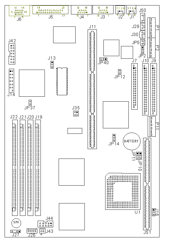
Aptiva - 2134/2176 System board layout & locations (Type A-1)
Applicable to: World-Wide
System Board Layout - Type A-1:

System Board Locations - Type A-1
J1 Keyboard connector
J2 Mouse connector
J3 Serial Port A connector
J4 Serial Port B connector
J5 Parallel Port connector (Printer)
J6 Monitor signal connector
J7 Diskette drive connector
J9 Primary Hard Disk IDE (Hard Disk 1, Hard Disk 2)
J10 Secondary Hard Disk IDE (Hard Disk 3 or CD-ROM, Hard Disk 4)
J11 Riser Connector¬PCI/ISA
J13 System board flash jumper (Normal: 1-2)
J14 VESA video feature connector
J16 L2 Cache Module SRAM Type (Normal: 2-3)
J19 RAM 72-pin memory SIMM Socket - Bank 1
J20 RAM 72-pin memory SIMM Socket - Bank 2
J21 RAM 72-pin memory SIMM Socket - Bank 3
J22 RAM 72-pin memory SIMM Socket - Bank 4
J26 LED connector (Power: 1-2, Hard Disk Drive: 3-4)
J27 Internal speaker (Enable: 1-2, Disable: open)
J29 Power Supply 2-pin connector (on/off switch)
J30 Power Supply Aux. 3-pin connector
J35 System board clock speed selection
J42 Internal monitor connector
J43 Processor fan connector
J44 Feature connector
J50 +12 V dc power connector for external speakers
J51 Cache connector
JP2 Smart Energy System (SES) supply present (Normal: 2-3)
JP5 Wake Up on Ring connector.
JP10,JP11 Internal/external Processor speed jumpers
JP12 Mouse enable (Enable: 1-2, Disable: 2-3)
JP14 CMOS, Power-on Password Reset (Normal: 1-2, Clear: 2-3)
JP37 On-board video enable (Enable: 1-2, Disable: open)
JP40 Keyboard, Mouse disable jumper (Enable: 1-2, Disable: 2-3)
P1 Power supply connector
P2 Power supply connector
P11 3.3 V dc power supply connector
U1 Processor
|
Search Keywords |
| |
|
Hint Category |
System Boards, Jumper/Switch Settings, Hardware Installation/Configuration | |
|
Date Created |
27-08-96 | |
|
Last Updated |
18-03-99 | |
|
Revision Date |
16-03-2000 | |
|
Brand |
IBM Aptiva | |
|
Product Family |
Aptiva | |
|
Machine Type |
2134, 2176 | |
|
Model |
| |
|
TypeModel |
| |
|
Retain Tip (if applicable) |
| |
|
Reverse Doclinks |