
|
452.602 bytes |
Service Hints & Tips |
Document ID: DETR-3X3FQ4 |
|
This document is provided to IBM and our Business Partners to help sell and/or service IBM products. It is not to be distributed beyond that audience or used for any other purpose. |
Aptiva - 2153-E3N: Incorrect Planar FSB Configuration
Applicable to: United States
Issue: Some Aptiva systems were incorrectly configured with 66Mhz Front Side Bus (FSB).
Systems Affected: Any 2153-E3N system shipped on or prior to July 29 should be checked using the procedure below.
Helpcenter Procedures:
Call takers that speak with customers who have an Aptiva 2153-E3N shipped on or before should perform the following:
- Walk the customer through the procedure
- Only if the customer is reluctant to do this simple procedure and only as a 'last resort' should they be referred to a servicer or place of purchase. The two affected retailers have received this procedure directly.
** IMPORTANT: Tracking Information**
- Once the planar has been reconfigured, place "**100**" in the text of the case prior to closing the case.
- Use the Tracking Code that references E3N 100MHz FSB Reconfiguration. (Code will be available shortly)
====================================================
IBM has recently determined that some Aptiva 2153-E3N computer systems were inadvertently misconfigured at the factory. As a result, while they may appear to operate normally, these systems are not able to take full advantage of the 100MHz Front Side Bus (FSB). This only applies to the E3N; other IBM Aptiva PC models are not affected.
IBM and your retailer want to ensure that your system performs at its full capability. Therefore, we have developed the following simple instructions that you may use to ensure that your 2153-E3N system is configured for optimum performance. If you have any questions regarding these instructions, you may call the IBM PC HelpCenter at (919) 517-2800. Owner Privileges members may call 1-888-PRIVILEGES (774-8453).
Aptiva 2153-E3N Configuration Verification Instructions
To verify that your system is configured for optimal performance please follow the steps below. The only tools that you will need are a Phillips head screw driver and a ball point pen. The entire verification procedure should take approximately 30 minutes.
1. Follow the Aptiva set up poster instructions to connect the monitor, keyboard and mouse to your tower. Turn on your tower, and wait for the operating system to be fully loaded so that your Windows desktop is displayed. Then from the “Start” menu, choose “shut down” then click on “yes” to power off your tower.
2. UNPLUG your tower from all external power sources and disconnect all external cables and devices (e.g. keyboard, mouse, speakers etc.).
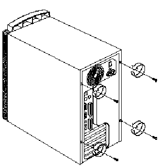
3. Remove the four Phillips head screws from the back of the tower. See Diagram 1.
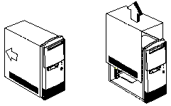
4. Remove the cover by pulling it towards the rear of the system. Lift the cover off the tower and set it aside. See Diagram 2. The Aptiva Reference Guide has further instructions on removing the cover.
5. Lay the tower on its side so that the bottom (side with the rubber feet) is facing towards your body.
6. The "floor" of the computer, a green surface onto which all components are attached, is called the motherboard (sometimes also called the "planar" or "mainboard"). On the motherboard there are three sets of switches labeled "SW1", "SW2" and "SW3"” "SW1" is located near the top of the motherboard, "SW2" is located vertically to the right of the DIMM sockets, and "SW3" is located above the CPU. We recommend you cut the white plastic tie wrap that is around the 3 grey ribbon cables with a pair of household scissors. This will allow easier access to the switches below. Be very careful not to cut the grey ribbon cables or any surrounding wires.
7. Please see the Diagram 3 for the exact switch locations.
8. You need to ensure that these switches are set correctly to ensure proper configuration of your system. The correct positions for the switches are as follows:
- SW1 should be: #1 OFF, #2 ON, #3 OFF, #4 OFF
- SW2 should be: #1 OFF, #2 ON, #3 OFF, #4 OFF, #5 OFF, #6 OFF, #7 ON, #8 OFF
- SW3 should be: #1 ON, #2 ON, #3 ON, #4 ON
9. Use your ball point pen to gently change any of the settings as required so that the settings match those listed above. Once you have finished, double-check to ensure that the proper settings have been made.
10. Replace the tower cover and the four Phillips head screws. Follow the set up poster instructions to connect the monitor, keyboard, mouse, etc. to the tower. See the Aptiva Reference Guide for additional instructions. **NOTE: the next time you turn on your Aptiva system, you will receive the following messages, which should be ignored:
“0127 CPU clock mismatch”
“0162 Equipment configuration error”
Press enter to continue the start-up process. You should not see these messages during subsequent start-ups.
Remember: you can register your system on Update Connector to automatically obtain select system software updates, hints, and performance tips for your IBM Aptiva system.
Thank you for you for your patience and understanding in this matter. We hope that you enjoy your new IBM Aptiva PC. Come visit us on-line with AOL, CompuServe, Prodigy, or on the World Wide Web at http://www.pc.ibm.com/us/aptiva. You may also reach us by phone at (919) 517-2800.
===============================================================
Diagram 1

===============================================================
Diagram 2

===============================================================
Diagram 3

===============================================================
Note: Shaded switches must be adjusted.

|
Search Keywords |
Miscellaneous | |
|
Hint Category |
System Boards | |
|
Date Created |
05-08-98 | |
|
Last Updated |
28-10-98 | |
|
Revision Date |
28-10-99 | |
|
Brand |
IBM Aptiva | |
|
Product Family |
Aptiva | |
|
Machine Type |
2153 | |
|
Model |
E3N | |
|
TypeModel |
| |
|
Retain Tip (if applicable) |
| |
|
Reverse Doclinks |