
|
120.128 bytes |
Parts Information |
Document ID: DDSE-44JGUH |
Netfinity 3500 - Internal Drives, Expansion Bays, Drive Specifications and Types of Cables
Applicable to: World-Wide
Internal Drives
Several types of drives are supported, such as:
Diskette
Hard disk
Rewritable optical disc
Tape
Expansion Bays: The server comes with the following:
One 3.5-inch, 1.44 MB diskette
One 5.25-inch CD-ROM drive, and, in some models, a 3.5-inch hard disk drive.
The following illustration shows the server front view, with the side panel removed.

CD-ROM Drive: The server comes with an integrated drive electronics (IDE) CD-ROM drive.
Open Bays: The server's design accommodates 3.5-inch and 5.25-inch devices, such as hard disk, tape, and rewritable optical disk drives. The number and capacities of the hard disk drives vary by model.
For information on the supported types of drives and their installation, see "Drive Specifications" on page 66 and "Preinstallation Steps" (All Bays) on page 70.
Diskette Drive: The 3.5-inch, 1.44 MB 2 diskette drive uses 1 MB (unformatted) or 2 MB (unformatted) diskettes.
____________________________________________________________________________________
2 MB equals approximately 1 000 000 bytes; total user-accessible capacity may vary depending on operating environment.
The server comes with an IDE CD-ROM drive installed in bay 1 and a 3.5-inch diskette drive installed in bay 4. Some models come with a preinstalled 3.5-inch hard disk drive in bay 6; open-bay models come with bay 6 empty.
The following illustration shows the locations of the bays in the server.

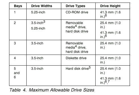
Drive Specifications: Table 4 describes some of the drive types that you can install in each bay, and their width and height requirements.

Types of Cables: The following cables are provided with the server:
Four-wire power cables connect most drives to the power supply. At the end of these cables are plastic connectors that attach to different drives; these connectors vary in size. Also, certain power cables attach to the system board.
Flat signal cables for connecting IDE and diskette drives to the system board. Signal cables are sometimes called ribbon cables. The following ribbon signal cables come with the server to connect IDE and diskette drives:
The IDE signal cable has three connectors. One of these connectors is attached to the CD-ROM drive, one is a spare, and the third attaches to the primary IDE connector on the system board.
One signal cable has one connector for attaching the diskette drive to the diskette-drive connector on the system board.
A flat SCSI signal cable for connecting devices to the SCSI adapter.
The server is equipped with an UltraSCSI controller, it has a ribbon cable that is connected to the internal SCSI hard disk drive. One end of this cable is connected to the 68-pin, Channel A SCSI connector on the system board. This cable provides four connectors for attaching other internal SCSI devices. For correct termination, see "Termination Requirements" on page 69.
For more information about SCSI devices, see "SCSI Drives" on page 68.
______________________________________________
3 To properly install a 3.5-inch drive in bay 2, use the 3.5-inch conversion kit for a 5.25-inch bay that is already installed in bay 2. If you are installing a 5.25-inch drive in bay 2, you must first remove the conversion kit.
4 Removable media include &cd.s, optical discs, diskettes, and tapes. However, the server only supports one diskette drive (standard in bay 4).
5 In some models, the &cd. drive might be set as the default startup (or boot) drive. However, if a hard disk drive is preinstalled, you can change the startup sequence, and specify the hard disk drive as the startup drive. See Start Options on page 21 for information about changing the startup sequence.
6 Drives that are higher than 41.3 mm (1.6 in.) cannot be installed.
7 One slim-high drive has a height of 25.4. mm (1.0 in.). One half-high drive has a height of 41.3 mm (1.6 in.). Therefore, you can install two slim-high drives or one half-high drive between bays 5 and 6.
|
Note |
The following are some important points to remember when connecting power and signal cables to internal drives:
The diskette drive, hard disk drive, and CD-ROM drive that are preinstalled in the server come with power and signal cables attached. If you replace any drives, it is important to remember which cable is attached to which drive.
When you install a drive, ensure that the connector at the end of the signal cable is connected to the system board.
If two IDE devices are used on a single cable, one must be designated as the primary or master device and the other a secondary or subordinate device; otherwise, some of the IDE devices might not be recognized by the system. The primary or secondary designation is determined by switch or jumper settings on each IDE device.
In this server, the CD-ROM drive is the primary device. If you install a second IDE device, it must be the secondary device. To attach an external SCSI drive, you must install an appropriate adapter in the server.
|
Search Keywords |
| |
|
Document Category |
Diskette Drives, Hard Drives, Optical Drives, Tape Drives | |
|
Date Created |
27-01-99 | |
|
Last Updated |
27-01-99 | |
|
Revision Date |
27-01-2000 | |
|
Brand |
IBM PC Server | |
|
Product Family |
Netfinity 3500 | |
|
Machine Type |
8644 | |
|
Model |
| |
|
TypeModel |
| |
|
Retain Tip (if applicable) |
| |
|
Reverse Doclinks |