
|
55.045 bytes |
Service Hints & Tips |
Document ID: DETR-44HJCE |
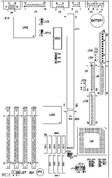
Aptiva - 2144/2168 (SL-C) C-2 system board layout and locations
Applicable to: World-Wide

--------------------------------------------------------------------------------
5.1.4 Type C-2 System Board Locations
Note: Jumpers must be checked for proper settings.
J1 Keyboard
J2 Mouse
J3 Serial Port A
J4 Serial Port B
J5 Parallel Port
J6 Monitor Signal
J7 Diskette
J8 Power
J9 Hard Disk Drive IDE (Factory-Installed Hard Disk 1, Hard Disk 2)
J10 Hard Disk Drive (Hard Disk 3 or CD-ROM, Hard Disk 4) See "Hard Disk Drive Jumper Settings for Connectors J9 and J10" in topic 5.4 of the HMM.
J11 Riser Connector--ISA AT bus
J14 VESA Video feature connector
J15 Video Disable (Normal: 1, 2)
J16, J17 Cache Jumpers (see Figure 4-15 in topic 4.1.11 of the HMM)
For SIMM installation, see "SIMM Configurations" in topic 5.6 of the HMM:
J19 RAM 72-pin memory SIMM Socket - Bank 3
J20 RAM 72-pin memory SIMM Socket - Bank 2
J21 RAM 72-pin memory SIMM Socket - Bank 1
J22 RAM 72-pin memory SIMM Socket - Bank 0
J23, J24 Processor jumpers ("Type C-2 Processor Jumpers"  )
)
J26 LED Connector (Power: 1, 2 Hard Disk Drive: 3, 4)
J27 Speaker (EMEA only--Enabled: 1, 2; Disabled: open)
J29 Power Supply 2-pin (on/off switch)
J30 Power Supply 3-pin
J34 Riser Connector--VESA local bus
J35, J36, J37 Processor Speed jumpers (see "Type C-2 Processor Speed Settings (J35, J36, J37)"  )
)
J38 Cache Jumper (see Figure 4-15 in topic 4.1.11 of the HMM)
JP3, JP4 VESA local bus jumpers (VESA: 1, 2 PCI: 2, 3)
JP5 Modem Wake Up on Ring
JP7 VESA local bus connector
JP13 VESA local bus jumper
JP14 Password Clear (Normal: 1, 2; Clear: 2, 3)
U6 486SX, 486SX2, 486DX, 487, 486DX2, 486 OverDrive, or Pentium ODP Processor
U22 System BIOS
U46 Video Controller
Cache banks 1 and 2 must both be filled for 256KB cache memory. For 128KB, fill Bank 1 only. See "Type C-2 Cache Memory Module Upgrades" in topic 5.1.8 of the HMM.
U20, U26, Cache Memory Sockets, Bank 1
U31, U32
U19, U25, Cache Memory Sockets, Bank 2
U29, U30
U36 Cache Memory Tag Address Socket
|
Search Keywords |
| |
|
Document Category |
System Boards, Jumper/Switch Settings | |
|
Date Created |
26-01-99 | |
|
Last Updated |
27-01-99 | |
|
Revision Date |
| |
|
Brand |
IBM Aptiva | |
|
Product Family |
Aptiva | |
|
Machine Type |
2144, 2168 | |
|
Model |
62P; 66P; 67P; 766; 866; 784; 785; 787; 887; 789; 889; 786; 782; 788; 888; 792; 856; 857; S86; S82; H89; L89; K89; H90; L90; K90; Y78; Y84; X79; Y79; X89; Y89; 26J; 68J; 62J; 27J; 28J; 63J; 64J; 65J | |
|
TypeModel |
| |
|
Retain Tip (if applicable) |
| |
|
Reverse Doclinks |