|
Notice: I have NO
personal experience with any Radisys EXM related system or
components. All these files were retrieved via Internet
Archive and were re-named to a shorter format. To me, there
can only be one period in a file name, or you may get odd
problems with web pages...
Use of any of the files or information on this page is
AT YOUR OWN RISK. If you want
a guarantee on this stuff, seek out any repair / service
company that supports EXM / EPC devices.
If you have any files or experience with these devices, please reach to
Louis Ohland.
EXM-PS50 Power Supply
Fits INSIDE of EXM slot! -DC12, -DC24, -DC48)
EXM-PS50 Manuals
EMC-PS50 Power Supply
Fits outside of EXM chassis 115/230 V
EMC-PS50 Manuals
|
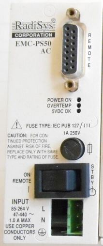
REMOTE - Female DB15 used to provide
remote control of power supply and to signal
the CPU through the backplane.
POWER ON - PSU providing power to backplane.
OVERTEMP - lit > 80* C. At 100* C, PSU
shuts off.
5VDC OK - 5V output voltage > 4.6V.
Fuse - IEC Pub. 127/III, 1.0A 250V (AC model)
ON / STBY - Internal circuits are live even
though power switch is in STBY (standby)
position.
INPUT - 18x3 AWG type SVT or SJT cable
What the heck is the model of the green receptacle?
|
|
EMC-PS50-AC |
EMC-PS50-DC12 |
EMC-PS50-DC24 |
EMC-PS50-DC48 |
| Input voltage |
85-264 VAC,
47-440 Hz |
10-20 VDC |
21-32 VDC |
40-64 VDC |
| Max input current |
1.0 A |
9.0 A |
6.0 A |
3 A |
| Fuse type |
IEC Pub. 127/III, 1.0A 250V |
IEC Pub. 127/I, 10A 250V |
IEC Pub. 127/I, 6.3A 250V |
IEC Pub. 127/I, 3.15A 250V |
EMC-PS50 INPUT Receptacle
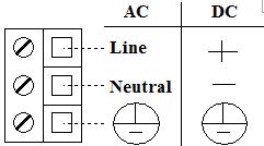
Pluggable Terminal Block
5.08 mm, 3 Positions

If you got an EMC-PS50 without the mating plug, this is
the part. Look for "Pluggable Terminal Block" with
5.08 mm pitch spacing and 3 Positions. Whatever
manufacturer, it needs to be able to take a minimum 18 AWG
conductor, 250v at 1A.
REMOTE Connector

|
| Pin |
Signal |
Pin |
Signal |
Pin |
Signal |
| 1 |
GND |
6 |
IRQ+ |
11 |
OT+ |
| 2 |
FLT- |
7 |
RST+ |
12 |
SD- |
| 3 |
OT- |
8 |
+5V EXT |
13 |
IRQ- |
| 4 |
(not used) |
9 |
GND |
14 |
RST- |
| 5 |
SD+ |
10 |
FLT+ |
15 |
+5V EXT |
|
+5V EXT Current limited +5V output with max of 1A.
GND This is chassis/logic ground.
All of these signals occur as pairs (+ and -).
Output signals will provide an uncommitted optoisolator
collector/emitter, rated at 50V max, 50mA max. The
phototransistor conducts whenever the particular condition
exists. Therefore, applying 5V to the + signal and
GND to - signal will provide a TTL level output.
Input signals require a 5V potential to be applied across
the pair to signal the condition.
FLT FAULT output when 5V output falls
below 4.6V.
OT OVERTEMP output when heatsink
temperature exceeds 80* C.
SD SHUTDOWN input remotely turns PSU on
or off. Active only when front-panel power switch is
in ON/REMOTE position. As long as a 5V potential
exists across these two lines, the PSU will remain in
standby mode and will not provide power to the backplane.
When the potential no longer exists, the PSU will again
power the backplane.
IRQ INTERRUPT input signals IRQ15 on
backplane. This is a buffered (inverted) input.
Since IRQs are positive edge-triggered (with pull-up
resistors), to signal the interrupt, apply a voltage
across these 2 lines for a minimum of 100
microseconds. This sets IRQ15 low. When the
power is removed, the pull-up resistor returns the line to
+5V causing a positive edge which triggers the interrupt.
RST - RESET input signal causes remote
hardware reset of CPU on backplane.
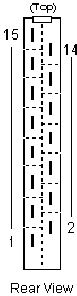
Rear Connector
15-pin male T&B/Ansley 371-21530-305X (or equivalent).
The female connector is a T&B/Ansley 376-21530-095X (or equivalent).
|
| Pin |
Signal |
Pin |
Signal |
| 1 |
ACF- |
2 |
ACF+ |
| 3 |
IRQ- |
4 |
IRQ+ |
| 5 |
RST- |
6 |
RST+ |
| 7 |
(not used) |
8 |
-12V |
| 9 |
+12V |
10 |
GND |
| 11 |
GND |
12 |
GND |
| 13 |
+5V |
14 |
+5V |
| 15 |
+5V |
|
|
|
Rear connector signals IRQ and RST (+ & -) are provided
to pass the front-panel remote connector signals through to
the backplane. These signals are defined below under the
remote connector section. In addition, when using the
EMC-PS50-AC power supply, ACF (AC Fail + & -) is
provided to signal a processor when the AC input
fails. ACF is tied to -I/O Channel Check on the
backplane.
Cooling Requirements The
unit is convection cooled, so no forced air in or around the
unit is required. However, the system should be
installed so that a minimum of 5" of air space is provided
on each of the three exposed sides of the power supply
unit. The heatsink temperature must not exceed 80°C.
|