|
PSL Explorer 1.1 Maybe? PSLDEV1.SYS version 1.1 (9103)
PSL Explorer 0.90 (from WinWorld PC) (User's Guide)
PSL Explorer 1.0 (from "Cathode Ray Dude")
PSL Support Diskette 1.0 (from "Cathode Ray Dude")
PSLDrivers PSLDEV1.SYS 1.00 (8905), 1.1 (9103), 2.00 (9208), 2.10 (9303), 2.20 (9605)
PSLJRC07.C Demo Of Temperature And Distance Probe Software (TURBO C 2.0)
Thanks to David Ress
DEVICE.EXE Loads and unloads PSLDEV.SYS (TXT file and COM inside)
If you have documentation or actual experience with the PSL,
we would like to hear it.
EPROM or Downloadable Microcode?
PSL DOS Device Driver Microcode (PSLDEV1.SYS)
-Version 1.0 - 05/31/89 4,406
-Version 1.1 - 03/21/91 4,912
-Version 2.0 - 08/13/92 7,736
-Version 2.1 - 03/22/93 7,738
-Version 2.2 - 05/04/96 7,789
Why do they refer to this as microcode?
If it was / is microcode, that would make updating the PSL
SIMMple-dimple. One thought is that loading microcode during
boot would negate the need for upgrading an EPROM, plus
overcome any issues with EEPROM or flash cycles.
Silk screening on David Ress' base unit (from 4991) says
"80C51". It uses an 87C51, so MAYBE the first PSLs
used 80C51s, then the later PSLs used 87C51s.
DOS Device Driver and DEVICE.COM
Normally, CONFIG.SYS loads all device drivers, including the
PSL Device Driver PSLDEV1.SYS. When memory is critical, it
can be useful to load and unload device drivers dynamically.
A small utility named DEVICE.COM is included with PSL
Explorer. This utility manages character device drivers such
as PSLDEV1.SYS. To use it, modify the PSL.BAT file that
invokes PSL Explorer. For example:
C:
CD\PSL\EXPLORER
DEVICE /i PSLDEV1.SYS /N:1
METASHEL /k
PSLEXPLR.EXE 60 /;
METASHEL /i
DEVICE /u
The first invocation of DEVICE loads PSLDEV1.SYS; the second
unloads it. The example above must be modified appropriately
for your installation: be sure the parameter for PSLDEV1.SYS
calls out your COM ports. New installations using PSL
Explorer 3 install using DEVICE.COM.
DEVICE.COM is a product of Cinch Industries, Boulder,
Colorado.
Serial Port Address
The PSL device driver (PSLDEV1.SYS) uses the IBM PS/2 family
communications port standard for the address and interrupts
(IRQ).
COM PORT  HEX ADDRESS    IRQ
   1         03F8       4
   2         02F8       3
   3         03E8       3
   4         02E8       3
The cable that comes with PSL is made to connect to a 25-pin
D-Shell. If your computer has a 9-pin D-Shell, you can buy a
9-pin to 25-pin adapter. Radio Shack has one with part
number 26-209. IBM has one also, with part number 6450242.
"PSL device drivers are available in the Users Guide that
allow highly technical customers to program their own
applications."
The normal install program sets the device driver statement
in CONFIG.SYS as follows:
DEVICE=C:\PSL\PSLDEV1.SYS /n:12
or
DEVICE=C:\PSL\EXPLORER\PSLDEV1.SYS /n:12
The /n:12 enables COM ports 1 and 2 to run PSL. If the mouse
is connected to COM1 change the device driver statement to:
DEVICE=C:\PSL\PSLDEV1.SYS /n:2
or
DEVICE=C:\PSL\EXPLORER\PSLDEV1.SYS /n:2
Now PSL can only be run on COM2.
Base Unit 84F9096 (Base Unit)
The microcomputer “Brain Box” that
supervises all PSL operations. The Base Unit allows up to
four modules to be attached and provides the interface to
the host PC. Low power CMOS electronics and a durable case
make it ready for portable operation.
PSL Technical Reference 57F7937 (Base
Unit)
PSL Hardware Users Guide 57F7936 (Base
Unit)
Base Unit PCB
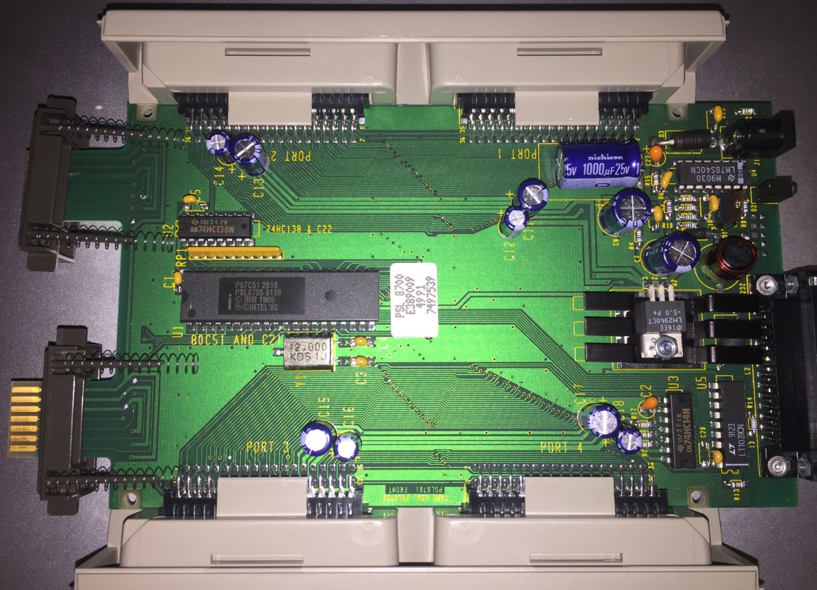
P87C51 8-bit CHMOS
Microcontroller datasheet
12.000 MHz xtal
LT1039CN RS232 Driver/Receiver with Shutdown datasheet
SN74HC138N Decoder Demultiplexer TI
Documents datasheet
SN74HC14N IC HEX Schmitt-Trigger
Inverter TI
Documents datasheet
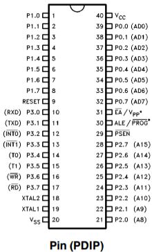
P87C51 Block Diagram

P87C51 Pin-Out
On-Chip Oscillator
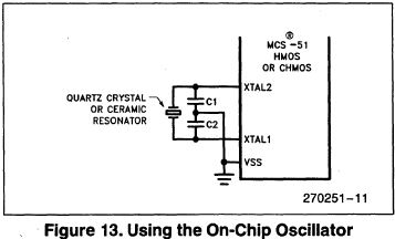
"To use the on-chip oscillator, connect
a crystal or ceramic resonator between the XTALI and XTAL2
pins of the microcontroller, and capacitors to ground"
See Y1, C3 and C4? Now it makes sense...
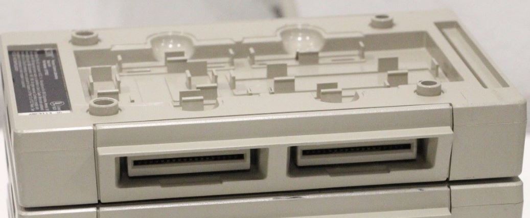
Looks like most of the secret sauce is
in the 87C51. Look at the -5.0v regulator. Nice heat sink.
See the electrolytic cap pair by each module port?
Made 4991. No corrosion.
Note the 14 conductor edge cards on the
left. The upper three traces on each port look beefier,
power?
Spring loaded port covers? Makes me wonder if this isn't
like RI/RO ports... But this is an 8 bit CPU, these ports
are enough for serial communication.
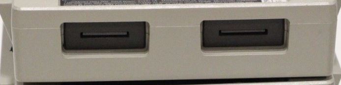
Looks like the grey plastic sides clip onto the side
ports.
When my hardware guide arrives, I'll be scanning...
Power Supply 57F7931 (Base Unit)
115 VAC wall mounted, UL listed supply
that powers the entire PSL system. Output is 8 volts DC at
1 ampere.
Steed Magnet Products Enterprise Co.,
Ltd. catalog
Page 92, physical
Model F5-DC81A-F2
F5 - 120v input, 3 prong (dummy ground prong...) Steed
case 48
DC - rectified and filtered DC output
81A - 8 (v) at 1A
F2 - DC plug I.D. x O.D. x L F2 2.5x5.5x12
Note: Center Positive!
PSL Battery Module PSL7200
The PSL Battery Module connects to one of the Base Unit
Module Ports and powers the Base Unit, Modules and Probes
for 8 to 24 hours. This allows PSL to be used with laptop
or palmtop computers in the field, providing a completely
portable system. Rechargeable batteries with a built-in
charger make it easy to power up.
Simply plug the Battery Module into any one of the four
PSL module ports. Recharge by connecting the PSL power
supply to the charging jack on the rear of the Battery
Module.
High capacity nickel metal hydride rechargeable batteries.
Built in charging circuit with automatic shutoff.
Completely overload and thermally protected.
Can be used as a backup supply for PSL for long
experiments.
Multiple Battery Modules can be used together to extend
the total running time.
Auxiliary power jack can be used to power the PSL Laser
Source or other 5 volt devices.
The PSL Battery Module uses the Base Unit AC power supply
for charging. It is completely overload and
over-temperature protected.
Battery Type: 1800 milliamp hour Nickel
Metal Hydride
System Power: 7.2 volts DC @ 3 amperes
Auxiliary Power Jack: 5 volts DC @ 1.25
amperes
Communications
Cable 57F7932 (Base Unit)
A 1.5 meter shielded RS-232 cable that
attaches Base Unit to Host PC’s Serial Port .
Note: "Straight
through" wired. Do NOT
use a "Null Modem" cable!
Make sure your communications cable between the computer
is not a "null modem" cable. These cables are not
compatible with PSL. PSL will not run with a null modem.
There are also null modem 9-pin to 25-pin adapters that
won't work. The rule is "No null modem cables or null
modem adapters". To determine if a cable is a null modem
cable, assuming both the cable's box and the cable don't
say NULL, you will need a continuity tester of some kind.
Remove any adapters or hardware attached to the cable in
question.
25-pin connectors >OR< 9-pin connectors at both
ends:
On a "straight through" serial cable,
pin 2 is connected to pin 2 at both ends. On a null modem
cable, pin 2 is connected to pin 3 at the other end. See
illustration for pin numbers.
25-pin connector at one end, and a 9-pin connector at the
other end:
On a "straight through" serial cable, pin 2 is connected
to pin 3 at the other end, and a null modem cable would
have pin 2 connected to pin 2. See illustration for pin
numbers.
|