VESA’s VGA BIOS
Extension (VBE) Standard
Windows/DOS
Developer’s Journal v3 n10 Oct 92 Page
15-18, 21-22 physicalIntroduction
When IBM introduced the VGA in 1987, it had a maximum resolution of 640 horizontal x 480 vertical pixels with 16 colors. The VGA could also reach 320 horizontal x 200 vertical pixels with a 256-color palette. Less than two years later, third- party manufacturers began delivering VGA-compatible cards that provided higher and higher graphics resolutions. These “SuperVGAs” now support several additional graphics modes from 800 x 600 x 16 to 1280 x 1024 x 256 and beyond. Unfortunately, each manufacturer has taken a different approach to the problems of mode initialization, mode resolution, and video memory windows. Even worse, these technical details are difficult to research, rarely compatible, and subject to change without notice. The net result is a learning curve steep enough to discourage even experienced developers. Fortunately, VESA has stepped forward to clear the tangle of conflicting SuperVGA implementation details and simplify life for the software developer.
What Is VESA?
The Video Electronics Standards Association (VESA) was born when several monitor and graphics adapter vendors met at spring COMDEX in 1989. Their initial purpose was to standardize video timing parameters for the relatively new SuperVGA 800 x 600 graphics mode. Without standardized video timing parameters, monitors require sophisticated synchronization electronics to handle every possible implementation of each video mode. The current VESA membership includes more than 130 graphics hardware and software vendors including Intel, Microsoft, IBM, Compaq, AT&T, and others. VESA has expanded to encompass standardization committees for SuperVGA graphics, XGA graphics, monitor timing, multimedia, and GUI accelerators. Most recently, VESA formed the Local Bus Committee to standardize VGA chipset interfaces with direct 32-bit CPU connections on the motherboard.
One of VESA's most important contributions to graphics software development has been the standard VGA BIOS Extension (VBE). In the remainder of this article, I cover the history behind today's standard and tell how you can take advantage of its deep color support.
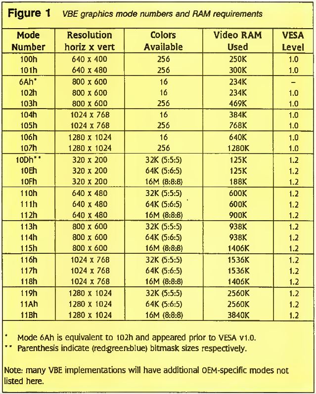
Figure 1 VBE graphics mode numbers and RAM requirements
Evolution of a Standard
VESA's first graphics software standards venture was a simple BIOS extension for initialization of the 800 x 600 x 16 SuperVGA display mode. This standard (#VS890401) was ratified by the VESA membership in August 1989. By November 1989, the SuperVGA committee had updated the standard to include both higher and lower resolutions (see Figure 1). This new standard, named VBE v1.0 (#VS891101), now covered resolutions from 640 x 400 x 256 all the way up to 1280 x 1024 x 256. VBE v1.0 also added a half-dozen functions necessary to provide a truly vendor-independent model for SuperVGA programming.
Figure 2 VBE text mode numbers and RAM requirements
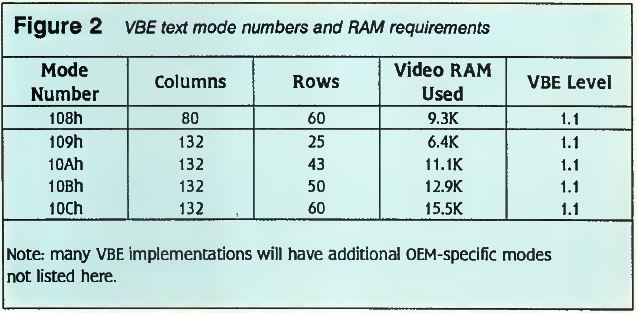
In October 1990, the SuperVGA committee officially adopted VBE v1.1 standard (#VS900602). VBE v1.1 added the first extended text modes with up to 132 columns of text (see Figure 2). Extended text modes, like graphics modes, had been another area notorious for vendor-dependent implementation. Additionally, VBE v1.1 added new functions to allow for video memory buffers larger than the active display area. This means the screen window can pan and scroll around the video memory buffer.
The SuperVGA committee announced the latest standard, VBE v1.2 (#VS911022), in October 1991. The VBE v1.2 standard has added 15 more high-resolution SuperVGA video modes. These new video modes support “deep color" displays with up to 24 bits of color per pixel. VBE v1.2 also includes the functions and data structures necessary to control the deep color modes.
You can now obtain TSRs which implement VESA functionality from virtually all SuperVGA adapter vendors including: ATI Technologies, Everex Systems, Genoa Systems, Orchid Technology, Paradise, Sigma Designs, STB Systems, Tecmar, and Video 7. Additionally, many SuperVGA chipset manufacturers have pledged their support for VESA. SuperVGA adapters implemented with these chipsets can use VESA TSRs: Ap- pian Technology, Chips & Technologies, Cirrus Logic, Oak Technology, SMOS Systems, Trident, Video 7, and Western Digital. Contact your local dealer for the latest drivers.
New Direct Color Memory Models
The IBM VGA has remained unchanged since its original release and has thus always been limited to a maximum 256 simultaneous colors. However, third-party manufacturers have been delivering SuperVGAs with up to 16 million colors since 1990. Consequently, there has been an urgent need for an industry standard for deep color VGAs. VBE v1.2 has filled this standards gap for DOS developers in a timely manner.
Figure 3 Memory models supported by VBE
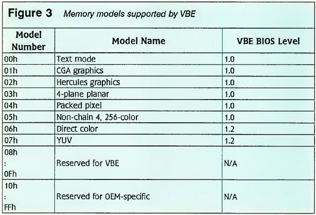
In the standard VGA, each of the 256 colors is defined by an entry in a palette lookup table. An entry consists of 18 bits defining one of 256K possible colors: 6 red bits, 6 green bits, and 6 blue bits. VESA refers to the number of bits per color element as the palette width. One approach to increasing the number of available colors is to switch to a “paletteless” memory model. Specifically, VBE v1.2 defines two new memory models for deep color: Direct Color and YUV. The complete revised list of memory models is shown in Figure 3.
Sidebar
How to Contact VESA
Video Electronics Standards Association (VESA)
2150 North First St., Suite #440 San Jose, CA 95131-2020 USA Phone: (408)435-0333 Fax: (408)433-8225 BiX: VESA
AOL: Keyword VESA CIS: GOVESA
VESA currently offers several publications of interest to developers. These can all be obtained free of charge from the VESA office.
“VESA Standard 800x600 Mode VGA BIOS Extensions:
VS890401 —April 9, 1989" (no revision number).
“VESA Super VGA Standard BIOS Extension: VS891101 —October 1, 1989”
(later known as VESA v1.0).
“VESA Super VGA Standard BIOS Extension, Revision A: VS900602 —June 2, 1990"
(internally documented as VESA v1.1).
“VESA Super VGA Standard BIOS Extension: VS911022 -October 20, 1991"
(internally documented as VESA v1.2).
“VESA Super VGA Programming Guideline for Direct Color Modes in VESA —January 10, 1991" (explains direct color mode numbering in VESA v1.0 through v1.2).
“VESA Video Cursor Interface: VS911021 —October 20, 1991"
(extends standard mouse and cursor interfaces for VESA resolutions).
“VESA Super VGA Protected Mode Interface: VS911020 - October 20, 1991”
(protected mode protocol for invoking VESA functions, does not use INT 10h).
“VESA VGA BIOS Extension Toolkit” (a diskette containing drivers, documentation, and demonstration programs from all of the SuperVGA vendors that support VESA. Some of the demonstration programs include source code. The current toolkit includes material from Appian Technology, ATI, Chips & Technologies, Cirrus Logic, Everex, Genoa, Orchid Technologies, Paradise, Sigma Designs, STB, Tecmar, Trident, Oak, and others).
Prior to VBE v1.2, the Direct Color and YUV memory models could only be supported under the provisions for vendor- specific extensions. VESA issued guidelines for Direct Color vendor-specific extensions as early as January 1991 (see sidebar). The original guidelines used the misnomer “True Color" rather than Direct Color and have since been amended.
Figure 4 Some common direct pixel organizations

The Direct Color memory model defines a pixel as a weighted color combination rather than as an index to a palette. Each pixel is composed of a bitmask with four bit-fields: RedMask, GreenMask, BlueMask, and RsvdMask (reserved). The size of each bitmask varies with each mode (see Figure 4) and ranges from five to eight bits long accordingly. The RsvdMask is allocated for the unused bits in a particular mode and normally ranges from zero to eight bits long. Figure 4 shows three possible organizations for 15-, 16-, and 24-bit Direct Color memory models. In the YUV model, the GreenMask, BlueMask, and RedMask substitute for the Y, U, and V components respectively.
Figure 5 Revised ModeInfoBlock for VBE v1.2
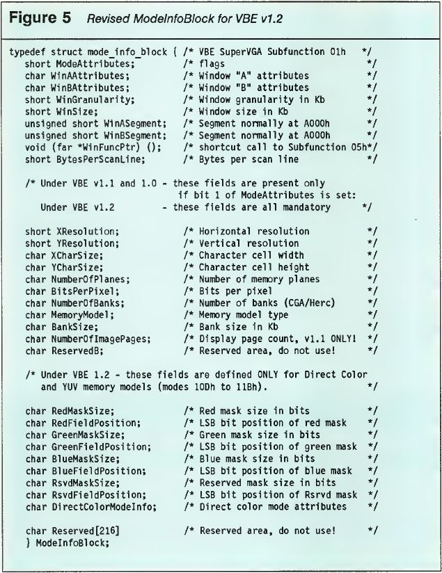
The actual organizations are flexible in both the size and position of each bitmask. The ModeInfoBlock structure as returned by the Return SuperVGA Mode Info subfunction (AL=01h) now includes the exact organization for the requested mode. See Figure 5 for the complete revised ModeInfoBlock structure.
The new DirectColorModeInfo field in the ModeInfoBlock contains important information about the exact video mode in question. Bit zero tells whether the color ramp (palette) of the Digital- to-Analog Converter (DAC) is fixed or programmable. As you may recall, the DAC is ultimately responsible for turning a set of bits into an analog level that your monitor can understand. If the color ramp is programmable, this implies the RGB palette lookup tables can be loaded by the standard BIOS Set Block of Color Registers function (INT 10h, AX=1012h). In standard VGA modes, this function can be used for dynamic color animation or other special effects. However, since the Direct Color model is paletteless by nature, the uses for programming the color ramp are very limited. For maximum portability, developers should avoid using the color ramp when in a Direct Color mode.
Bit one of the DirectColorModeInfo element tells whether the reserved bits (RsvdMask) are usable by your application. If bit one is true, then your application may read and write the reserved bits along with the rest of the pixel data. The reserved bits could be used to store invisible attribute data about the image that might normally reside in precious conventional memory. If bit one is false, the SuperVGA implementation denies you the ability to read and write these bits. Failure to honor this bit could result in unpredictable displays. For maximum portability, developers should design their applications to operate correctly with or without using reserved bits.
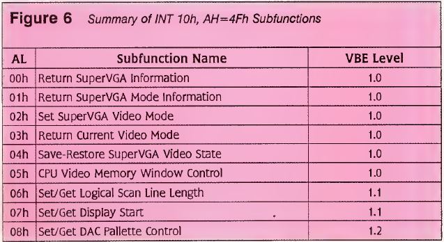
Figure 6 Summary of INT 10h, AH=4Fh Subfunctions
New DAC Palette Functions
VBE v1.2 includes two new functions to control the palette width. Figure 6 shows the revised list of functions and the minimum VBE BIOS level required to call them. As described earlier, the IBM VGA implementation sets the maximum palette width at 18 bits total with 6 bits in each RGB element. The new Set DAC Palette Control function enables the width of each primary (RGB) color element to be increased to 8 bits or more. The purpose is to enable 24-bit color definitions in the context of a palettized 256-color mode.
This is the primary alternative to using paletteless Direct Color models. Applications may continue to address memory the same way they would in a 256-color mode, but the palette indices actually refer to 24-bit values rather than 18-bit values. This method can often be incorporated into existing applications with fewer source code changes than the Direct Color method requires. Specifically, Set DAC Palette Control makes sense for VGA mode 13h as well as VBA SuperVGA modes 100h, 101h, 103h, 105h, and 107h (see Figure 1). The Direct Color modes 10Dh through llBh already have implicit palette width definitions.
The Set DAC Palette Control function returns in BH the number of bits per primary color element that it could actually set. If the SuperVGA is incapable of setting the requested width, it will decrease the width to the next lower value that it can handle successfully. Although VBE v1.2 does not limit the maximum number of bits per primary color element, it would be most unusual to have more than 10 bits per primary color element. Before calling this function, you should check the zero bit of the “capabilities” field in the VGAInfoBlock structure to see if this function is supported.
After adjusting the palette width, your application can load the color palette registers with the standard BIOS Set Block of Color Registers function (INT 10h, AX=1012h). This BIOS function should work with up to 8 bits per primary color element. Beyond 8 bits, an OEM-specific approach must be taken since the VGA data format specifies one byte per primary color element.
VBE v1.2 also provides the complementary Get DAC Palette Control function which simply returns the current number of bits per primary color element. The number of bits per primary color element is reset to six each time a VGA or VBE SuperVGA graphics mode change takes place.
Conclusion
The SuperVGA BIOS Extensions v1.2 are a significant upgrade to the previous VBE v1.1 standard. These enhancements consist of new Direct Color memory models, deep color graphics modes, and DAC palette control functions. The VBE v1.2 standard gives DOS developers a fighting chance to produce applications which break the VGA 256-color barrier in a hardware-independent fashion. If you are developing any DOS application which uses graphics, I recommend taking a close look to see how VBE can help you.
Annotated Bibliography
Ferraro, Richard F. Programmer's Guide to the EGA and VGA Cards. New York: Addison-Wesley, 1991. Contains the most exhaustive examination available of the EGA and VGA adapters. Includes a complete description of every register, graphics mode, text mode, font, and bitmap combination available. The second edition covers VBE v1.1 and SuperVGA programming.
Kliewer, B. “VGA to the Max - VESA makes software standard for Super VGA," BYTE 15, no. 13 (12/01/90), 355. An introduction to how VBE BIOS v1.1 supports various video windowing modes and functions. Explains the importance and evolution of SuperVGA standards.
Rosch, Winn. "Standardizing Super VGA: The Role of VESA,” PC Magazine 10, no. 13 (07/01/91), 126. A short informative article on the importance of standardized monitor timings and how VESA has contributed to it.
Volkman, Victor R. "The VESA BIOS Extensions for SuperVGAs," Tech Specialist 1, no. 7 (12/01/90), 12. An exhaustive examination of the VESA BIOS Extensions v1.1 including a complete C interface library and demonstration programs. The source code disk can be purchased from Windows/DOS Developers Journal for $5.
Victor R. Volkman received a BS in Computer Science from Michigan Technological University. He is a contributing editor for Windows/DOS Developer's Journal. He is currently employed as Software Engineer at Cimage Corporation of Ann Arbor, Michigan. He can be reached directly at the HAL 9000 BBS (313) 663-4173 or as vrv@cimage.com on Usenet