by Vinita Singhal, Altera Corp
EDN, January 20, 1992 pages 115-120, 122 physical
The Micro Channel Architecture defines a high-speed data-transfer protocol for moving data between a bus master and a slave. Implementing this protocol in programmable logic gives you design flexibility in addition to high-speed data transfers. Recent enhancements to the Micro Channel Architecture bus have created a system that supports independent bus masters. One of the main enhancements is the streaming-data procedure (SDP), which allows faster data transfer. Implementing this protocol needn’t greatly complicate your design. You can generate essential signals for a bus-master adapter with SDP capability using an EPLD-based design. (Check the EDN BBS for an Altera Hardware Description Language state-machine description of this circuit.)
Streaming is a high-speed data-transfer mode for data (bytes, words, or double words) that reside at consecutive address locations. An SDP cycle needs only the starting address; the protocol assumes subsequent data packets are at sequential addresses. One streaming-data cycle consists of multiple 16-, 32-, or 64-bit sequential data transfers. The cycle time for each packet transfer is half (100 nsec) that of the default (zero-wait-state, 200-nsec) cycle. The streaming-data procedure is transparent to devices that do not use or transmit the data. Streaming-data participants must support basic transfer to operate with non-streaming-data participants.
The SDP increases data-transfer rates by a factor of 2, 4, or even 8 over the 5 Mbyte/sec baseline bus throughput (which assumes 8-bit transfers). Any bit in the POS (programmable-option-select) register space can enable SDP. Data streaming can occur only by mutual consent between a master and a slave device and requires several signals. These signals are:
|
Signal |
Description |
Remarks |
|
-SDR(0) |
Streaming-data
request bit 0 |
Input
to MCA_BM EPLD |
|
-SDR(1) |
Streaming-data
request bit 1 |
Input
to MCA_BM_ EPLD |
|
-MSDR |
Multiplexed
streaming-data request |
64-bit
SDP using address + data buses |
|
-SD
STROBE |
Streaming-data
strobe |
MCA_BM
EPLD output |
|
CD
CHRDY |
Card
channel ready |
From
slave adapter to MCA bus |
|
CHRDYRTN |
Card
channel ready return |
Input
to MCA_BM _EPLD (generated by system as logical
AND of all adapter CD CHRDY signals) |
|
-CD
DS 16 |
Card
acknowledge |
16-bit
data stream |
|
-CD
DS 32 |
Card
acknowledge |
32-bit
data stream |
The following streaming-data-signal combinations (X is “Don’t Care”) are valid:
|
-SDR0 |
-SDR1 |
-CD DS 16 |
-CD DS 32 |
-MSDR |
Description |
|
0 |
0 |
X |
X |
X |
Reserved |
|
0 |
1 |
0 |
0 |
0 |
64-bit SDP |
|
0 |
1 |
0 |
0 |
1 |
32-bit SDP |
|
0 |
1 |
0 |
1 |
1 |
16-bit SDP |
|
1 |
0 |
X |
X |
X |
Reserved |
|
1 |
1 |
X |
X |
X |
Basic transfer |
Although the Micro Channel Architecture specification permits data transfers between unequal bus widths, it does not direct unequal bit-width data through the data-byte lanes during the SDP; the master or slave must implement this control. In general, the wider side of the transfer controls where the data end up. For example, in the case of a 16-bit master executing streaming-data transfers with a 32-bit slave, the slave provides steering control.
Five signals control the bus Once a bus master gains control of the bus, it drives all bus-control signals and the address and data buses. On the Micro Channel Architecture bus, a bus master must drive five bus-control signals. These signals are the -SO and -S1 status signals; the -ADL address de-code latch; the -CMD command strobe; and the M/-IO memory or I/O-cycle indicator.
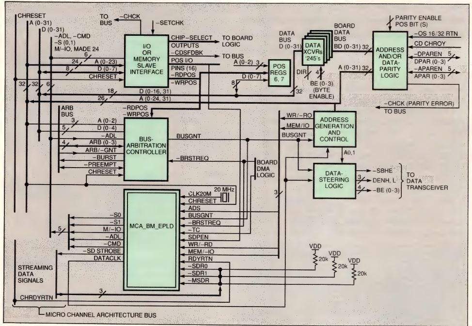
Fig 1—The Micro Channel Architecture bus interface uses three major functional blocks. These blocks are the memory/IO slave interface, an arbitration-controller block, and the MCA_BM__EPLD.
Fig 1 illustrates a complete interface to the Micro Channel Architecture bus using three major functional blocks: An I/O or memory slave interface, an arbitration-controller block (both available from Altera and several other sources), and the MCA_BM_EPLD (Altera’s Micro Channel Architecture Bus Master Erasable Programmable Logic Device), which implements bus-master control logic having SDP capability.
When the arbitration controller signals to the MCA_BM_EPLD, using -BUSGNT, that the EPLD has won the bus, the EPLD drives the bus-control signals. If you enable streaming-data capability (via a POS register bit), the MCA_BM_EPLD determines whether the slave can perform streaming operations. If so, the MCA_BM_EPLD generates the -SD STROBE (streaming-data strobe) signal. If the slave introduces wait states (CD CHRDY=low), -SD STROBE continues to strobe; however, the master maintains data on the bus until the slave activates CD CHRDY.
The MCA_BM_EPLD is a synchronous state machine that runs off a 20-MHz clock (CLK_20) and generates the signals necessary for a bus master with streaming-data-transfer capability. These signals are:
|
Signal |
I/O |
Description |
|
-ADL |
O |
MCA
address-decode latch |
|
-CMD |
O |
MCA
command strobe |
|
-S0 |
O |
MCA
status signal bit 0 |
|
-S1 |
O |
MCA
status signal bit 1 |
|
M/-IO |
O |
MCA
memory I/O signal |
|
-SD
STROBE |
O |
MCA
streaming-data strobe |
|
DATA_CLK |
O |
Master
internal clock, to board logic |
|
-ADS |
I |
Address
stable. from CPU, controller or
address-generator logic |
|
BUSGNT |
I |
Bus
arbitration controller output, signals bus won |
|
-BRSTREQ |
I |
Board
logic, burst request |
|
-TC |
I |
Board
logic/MCA, terminal count |
|
CHRESET |
I |
MCA
channel reset |
|
CLK_20M |
I |
20-MHz
synchronizing clock |
|
WR/-RD |
I |
Write/read
from CPU/controller or address-generator logic |
|
MEM/-IO |
I |
Memory
or I/O cycle, generated by CPU, DMA controller
or address generator |
|
-SDR0 |
I |
MCA
streaming-data request bit 0 |
|
-SDR1 |
I |
MCA
streaming-data request bit 1 |
|
-MSDR |
I |
MCA
multiplexed SDR (64-bit streaming-data
transfers) |
|
RDYRTN |
I |
MCA
CD CHRDYRTN |
|
SDPEN |
I |
From
any user-defined POS bit |
Within an SDP cycle, the -SD STROBE clock times each transfer. SDP cycles are of several types that depend on the conditions under which the SDP commences and whether the slave introduces wait states. These types are deferred cycle, where the SDP start is delayed; data pacing, where wait states are inserted in SDP cycles; and combined deferred cycle and data pacing. Additional SDP qualification depends on how the cycle is terminated. Termination can be requested by the master, the slave, or by the master because the slave isn’t ready. The MCA_BM_EPLD supports all variations of the SDP cycles.
The MCA_BM_EPLD’s outputs are decoded as a function of the present state. The next state results from the present state and the inputs. The main states of the MCA_BM_EPLD state machine (Fig 2) are:
|
State |
Description |
|
IDLE |
Idle, wait for cycle start |
|
STATUS |
Cycle start, drive status
signals |
|
ADLTCH |
Generate address-decode latch |
|
BXFER |
Distinguish the cycle to be
non-streaming |
|
WAIT |
Determine synchronous or
asynchronous extended |
|
CMDCLK1 |
Default cycle timing state |
|
SYNEXT |
Synchronous-extended cycle |
|
SYNEXT1 |
Synchronous-extended cycle
timing state |
|
ASYNEXT |
Asynchronous-extended cycle |
|
SDDEFCYC |
Deferred start for SD cycle |
|
SD STROBE |
Streaming-data strobe (active
low) |
|
STRBHI |
Streaming-data strobe (high) |
|
MTERM |
Master-terminated SD cycle |
|
STERM |
Slave-terminated SD cycle |
|
MSTERM |
Master-terminated SD cycle,
slave not ready |
|
MSTRBHI |
Streaming-data strobe (high,
slave not ready) |
|
CMDTR1 |
Trailing edge of –CMD |
|
EBC |
End of basic transfer cycle |
|
ESDC |
End of streaming-data-transfer
cycle |

Fig 2—The bus-master state machine contains 19 states that perform streaming- and nonstreaming-data transfers.
Several details of the state-transition diagram in Fig 2 are worth emphasizing. The signals -BUSGNT and -BRSTREQ tell the MCA_BM_EPLD when it is the bus master for block (burst) transfers. -BUSGNT is an output from the Micro Channel Architecture bus-arbitration controller logic, signaling that the EPLD has won the bus. The -BRSTREQ input to the arbitration controller indicates an active -BURST transfer request.
-ADS starts the transfer cycle
The -ADS input to the EPLD (Fig 1) indicates a valid address on the address bus. Functionally, -ADS is similar to the -ADS signal on the 80386 processor. This signal indicates the start of a data-transfer cycle and the MCA_BM_EPLD device uses it to latch the state of the WR/-RD and MEM/-IO signals. Subsequently, the MCA_BM_EPLD drives the status and control signals. The EPLD decodes the status signals (-S0 and -S1) and M/-IO from the state of the write/read signal (WR/-RD) and MEM/-IO inputs, respectively. One cautionary note, the Micro Channel Architecture bus doesn’t provide pullup resistors for the streaming-data-related signals (-SDR0, -SDR1, -MSDR, and -SD STROBE). As a result, adapters that receive these signals must provide pullup resistors for each signal. The Micro Channel Architecture specification recommends a minimum of 20-k0 pullup to 5V dc.
The DATA_CLK output on the MCA_BM_EPLD device provides stretched-out -SD STROBE pulses by tracking the status of the CHRDYRTN signal. The address and byte-count increment logic can use DATA_CLK directly. However, when -MSDR is low, indicating 64-bit data streaming, the Micro Channel Architecture specification (and hence, the MCA_BM_EPLD) does not support data pacing. In this case, the DATA_CLK output is identical to the -SD STROBE output.
The bus-master transfer controller indicates termination of the SDP cycle to the MCA_BM_EPLD de-vice by either of two conditions. One condition is the deactivation of BUSGNT followed by deactivation of the -BRSTREQ signal. If the master is -PREEMPTed or no longer needs the bus, the bus-arbitration controller deactivates BUSGNT. If another device
-PREEMPTs the bus master, the adapter has up to 7.8 usec to complete transfers. Under -PREEMPTion, the arbitration controller de-asserts BUSGNT but may continue to assert -BURST on the Micro Channel bus. You can use the falling edge of BUSGNT to start a 7.8-usec timer to monitor the requesting device’s de-assertion of its bus request (-BRSTREQ). To maximize bus throughput, the MCA_BM_EPLD uses BUSGNT inactive and -BRSTREQ inactive to terminate the cycle. The second termination condition is an active low pulse on the -TC input pin. The local-transfer controller generates this active-low, terminal-count signal to indicate the last streaming-data-transfer cycle.
According to the Micro Channel specification, a slave that introduces wait states during SDP should not de-assert –SDR0 and -SDR1 while CD CHRDY is inactive. Following an active CD CHRDY, the slave may de-assert the –SDR0 and -SDR1 signals. This restriction leads to the “Master-terminated, slave-not-ready” special case of a master-terminated streaming-data cycle.

Fig 3—This diagram illustrates the timing of a 16- to 32-bit streaming-data transfer, with deferred start and data pacing, terminated by the slave.
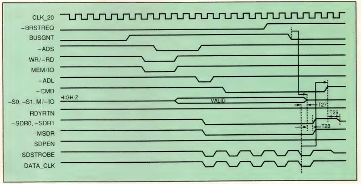
Fig 4—The bus master forcing -BRSTREQ high terminates a streaming-data transfer.
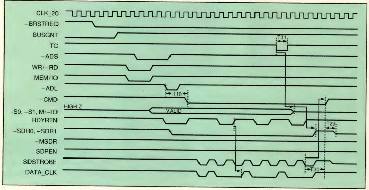
Fig 5—When the master terminates a bus request, if the slave is not ready, the master continues to generate -SD STROBE until the slave is ready.
The timing diagrams in Fig 3, 4, and 5 illustrate the bus cycles the chip supports along with all relevant timing parameters. Several of these timing parameters are dictated by the Micro Channel specification. They are not specific to the MCA_BM_EPLD; their inclusion makes the interface timing description complete and easy to understand. For cross-referencing, Table 1 contains the Micro Channel Architecture streaming-data timing parameter numbers.
Fig 3, 4, and 5 illustrate timing parameters for SDP cycles. For a deferred SDP cycle, the Micro Channel Architecture specification does not have a maximum number (minimum specification=0 usec) for the first active -SD STROBE pulse after CHRDYRTN becomes active. The timing of -SD STROBE after CHRDYRTN is MCA_BM_EPLD’s T23 (Fig 3). T24 refers to a Micro Channel Architecture specification that the slave wait-state logic must adhere to for CHRDYRTN timing. Timing parameters T25 and T26 specify setup and hold times for the slave wait-state logic for data-pacing, that is, introducing wait states during SDP cycles.
In a slave-terminated SDP cycle, the slave indicates the end of the SDP transfer by de-asserting –SDR0, -SDR1, and -MSDR. In response, the bus master de-asserts status signals -S0 and -S1 and the -CMD strobe. MCA_BM_EPLD’s T30 timing parameter adheres to the Micro Channel Architecture specification stating that -CMD inactive from the last falling edge of -SD STROBE should be 100 nsec minimum. T30 also applies to the case when the master terminates the cycle but the slave is not ready, which is illustrated in Fig 5.
In a master-terminated SDP cycle (Fig 4), the SDP transfer ends when the master deactivates –S0 and -S1. T27 refers to a Micro Channel Architecture specification that states -S0 and -S1 should be de-asserted within 10 usec of the last -SD STROBE pulse. This parameter makes it necessary for the transfer controller on the bus-master adapter to signal the end of SDP transfer (by de-asserting the BUSGNT signal) more than one CLK_20 period (50 nsec + EPLD-register set-up time) before the last -SD STROBE pulse.
Timing parameter T28 is a Micro Channel Architecture specification for the slave adapter to de-assert –SDRO0 -SDR1, and -MSDR signals within 40 nsec of the bus-master adapter’s de-assertion of the -S0, -S1 status signal. T29 is a parameter common to all of the SDP cycles. This parameter refers to a Micro Channel Architecture specification that states after the –SDR0 and -SDR1 signals are de-asserted, the slave must drive the -SDRO and -SDR1 signal to a high-impedance state within 40 nsec from the trailing edge of the -CMD strobe. The timing parameter T31 specifies the minimum required pulse width for -TC, the terminal-count signal that indicates the end of the SDP transfer, to be 60 nsec minimum. Table 1 gives device-specific timing information for the bus-cycle timing diagrams illustrated in Fig 3, 4, and 5.

Table 1: Streaming Data-Transfer Cycles
You could implement this design in several different technologies. However, using programmable logic offers you the ability to add other functions, remove unnecessary features, or modify parts of the design to meet your design needs.
Text Box
References
1. Micro Channel Adapter Handbook, April 1990, Altera Corp.
2. 1991 Altera Data Book, Altera Corp.
3. IBM Micro Channel Bus-Master Design-Seminar Notes, February 1990.
4. Personal System/2 Hardware Interface Technical Reference, May 1988.
5. IBM Micro Channel Architecture Supplement for the Personal System/2 Hardware Interface Technical Reference, November 1989.
6. Heath, C., “Overview of Extended Micro Channel Functions,” Personal Systems (IBM Personal Systems Technical Journal), Issue 4, 1989.
7. “Micro Channel Bus-Master Design Guidelines,” Application Note 23, January 1991, Altera Corp.
8. “Micro Channel Bus Master and SDP Logic with the EPM5032 EPLD,” Application Note 24, January 1991, Altera Corp.
Author’s biography Vinita Singhal is an MPLD Design Manager at Altera Corp who supervises the design group that transfers designs from EPLDs to Mask-Programmed Logic Devices. She has a BTech with honors from the Indian Institute of Technology and an MSEE from Pennsylvania State University. In her spare time, Vinita enjoys reading, technical writing, and traveling.