For all it's world straddling might, IBM didn't seem to clearly document the Refresh Cycle for system board / planar memory. This is starting the long, painful journey towards understanding how the Memory Controller refreshes the RAM. Each of the timing diagrams appears to concern itself with adapter cards in an MCA slot, NOT memory on the planar.
It seems reasonable that the Refresh Cycle for the planar memory resembles the Basic cycle, but with tweaks. No need to Write memory... Supposedly, memory refresh is done during the arbitration phase, not grant phase, or at least that might be for the planar memory.
MAJ Tom is coming home... [LFO]
PS/2 Model 80 Technical Reference Apr87 page 110
Pat Bowlds, MCA Revolution in Personal Computing, page 265
The ONLY timing chart that I've foundt so far...
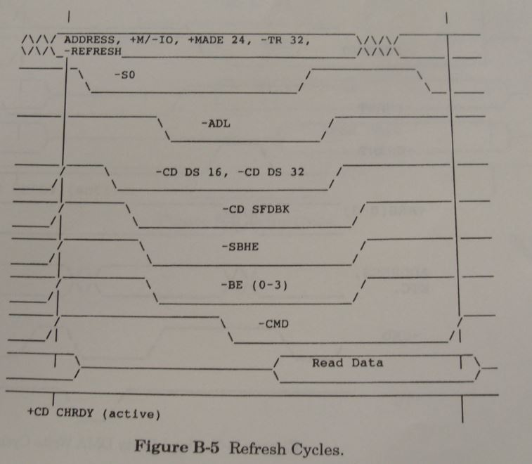
Since we can't findt a description for a Refresh Cycle, we'll adapt the Basic Transfer example to specifically describe the Memory Refresh cycle.
Simplified Basic Transfer Cycle
Most microprocessor and DMA operations transfer data with the same control sequence. For transfers other than MM transfers, the signals appear on the channel in the sequence:
1. Address bus, MADE 24, M/-IO, and -REFRESH (if applicable) become valid, beginning the cycle.
2. 'status' signals become valid.
3. 'address decode latch' (-ADL) signal becomes valid.
4. In response to an unlatched address decode, MADE 24, and M/-IO, the adapter returns:
• -CD SFDBK
• -CD DS 16 (if the attachment is capable of 16-bit operation).
• -CD DS 16 and -CD DS 32 (if the attachment is capable of 32-bit operation).
5. In response to an unlatched address decode, MADE 24, M/-IO, and Status, the adapter drives CH RDY inactive if the cycle is to be extended.
6. Write data appears on the bus (for the Write cycle).
7. -CMD becomes active and -ADL become inactive.
8. 'status' signals become inactive.
9. 'address' signals become invalid in preparation for the next cycle.
10. In response to an address change:
• -CD SFDBK is set inactive by the attachment.
• -CD DS 16 is set inactive by the attachment.
• -CD DS 32 is set inactive by the attachment.
11. If CD CHRDY has been set inactive, the system holds in this state indefinitely until CD CHRDY is set active. This line should not be held inactive longer than 3.0 microseconds.
12. The attachment places Read data on the bus in preparation for the trailing edge of -CMD (for the Read cycle).
13. The address, 'status' signals, and M/-IO for the next cycle may become valid.
14. -CMD goes inactive, ending the cycle.
Note: The address and Status can be overlapped with the preceding cycle to minimize the memory access time impact on performance.
Signal Definitions:
ADDRESS
M/-IO: Memory/-Input Output: This signal distinguishes a memory cycle from an I/O cycle. When this signal is high, a memory cycle is in progress. When M/-IO is low, an I/O cycle is in progress. M/-IO is driven with a tri-state driver.
MADE 24: Memory Address Enable 24: This line indicates when an extended address is used on the bus. If a memory cycle is in progress and MADE 24 is inactive, an extended address greater than 16MB is being presented; if MADE 24 is active, an unextended address less than or equal to 16MB is being presented. This line is driven by the controlling master and decoded by all memory slaves, regardless of their address space size. MADE 24 is driven with a tri-state driver.
TR 32: Translate 32: This line is driven inactive by 32-bit controlling masters and received by the Central Translator Logic. TR 32 can also be received by any 32-bit slave. When TR 32 is inactive, a 32-bit controlling master drives -BED through -BE3. When TR 32 is active, the Central Translator Logic drives -BED through -BE3. TR 32 must be driven by a tri-state driver. See "Channel Support" on page 32 for more information about Central Translator Logic.
-REFRESH: -Refresh: This line is driven by the system logic and is used to indicate that a memory refresh operation is in progress. While this line is active, a memory read operation occurs. The address lines contain the memory locations being refreshed. Nine lines, A0 through A8, are activated. -REFRESH timing may be inconsistent and must not be used as a timing mechanism. -REFRESH is driven with a tri-state driver.
-S0, -S1: -Status Bits 0 and 1: These lines indicate the start of a channel cycle and also define the type of channel cycle. When used with M/-IO, memory read/write operations are distinguished from 110 read/write operations. These signals are latched by the slave, as
required, using the leading edge of -CMD or the trailing edge of -ADL. -S0 and -S1 are driven with a tri-state driver.
-ADL: -Address Decode Latch: This line, driven by the controlling master, is provided as a convenient way for the slave to latch valid addresses and status bits. This signal can be used by slaves to latch the address from the bus. -ADL is not active during matched-memory cycles. -ADL is driven with a tri-state driver.
-CD DS 16 (n): -Card Data Size 16: This line is driven by 16-bit and 32-bit memory, I/O, or DMA slaves to provide an indication on the channel of a 16-bit or 32-bit data port at the location addressed. The (n) indicates this signal line is unique to each channel connector (one independent signal line per connector). This signal is unlatched and derived as a valid address decode. All system logic receives this signal to support communication with 16- and 32-bit slaves. -CD DS 16 is not driven by 8-bit slaves. All 16- and 32-bit slaves must drive this signal. -CD DS 16 is driven with a totem-pole driver.
-CD DS 32 (n): -Card Data Size 32: This line is driven by 32-bit slaves to provide an indication on the bus of a 32-bit data port at the location addressed. The (n) indicates this signal line is unique to a channel connector position (one independent signal per connector). -co os 32 is unlatched and derived from a valid address decode. All 32-bit slaves must drive this signal. -CD DS 32 is inactive for an 8- or 16-bit data port. -CD DS 32 must be driven with a totem-pole driver.
-CD SFDBK (n): -Card Selected Feedback: When the controlling master addresses a memory slave or an I/O slave, the addressed slave drives -CD SFDBK active as a positive acknowledgment of its presence at the address specified. The (n) indicates this signal line is unique to each channel connector (one independent signal line per connector). This signal is unlatched by any slave with a valid select decode, and is driven by any slave selected by any select mechanism except -CD SETUP. The slave does not drive -CD SFDBK during the configuration cycle. -CD SFDBK is driven with a totem-pole driver.
Note: Memory supporting diagnostic software must not drive -CD SFDBK during the diagnostic operation
-SBHE: -System Byte High Enable: This line indicates and enables transfer of data on the high byte of the data bus (D8 - D15), and is used with A0 to distinguish between high-byte transfers (D8 - D15) and low-byte transfers (D0 - D7). All 16-bit slaves decode this line, but 8-bit slaves do not. -SBHE is driven with a tri-state driver.
-BE0 - -BE3: -Byte Enable 0 through 3: These lines are used during data transfers with 32-bit slaves to indicate which data bytes will be placed on the bus. Data transfers of 8, 16, 24, or 32 contiguous bits are controlled by -BE0 through -BE3 during transfers involving 32-bit slaves only. These lines are driven by the controlling master when TR 32 is inactive, and by the Central Translator Logic (for those operations involving a 16-bit master with a 32-bit slave) when TR 32 is active. These lines are unlatched on the bus and, if required, must be latched by 32-bit slaves. -BE0 through -BE3 are driven with tri-state drivers.
-CMD: -Command: This signal is used to define when data is valid on the data bus. The trailing edge of this signal indicates the end of the bus cycle. This signal indicates to the slave how long data is valid on the bus. During write operations, the data is valid on the bus as long as -CMD is active. During read operations, the data is valid on the bus between the leading and trailing edges of -CMD, and must be held on the bus until after -CMD goes inactive. This signal can be used by the slaves to latch the address on the bus. Latched status lines gated by -CMD provide the timing control of valid data. Slaves should use transparent latches to latch address and status information with the leading edge of -CMD. -CMD is not active during matched-memory cycles. It must be driven with a tri-state driver.
Read Data
CD CHRDY (n): Channel Ready: This line, normally active (ready), is pulled inactive (not ready) by a memory or I/O slave to allow additional time to complete a channel operation. The (n) indicates this signal line is unique to each channel connector (one independent signal line per connector). During a read operation, a slave ensures that data will be valid on the data bus within the time specified after releasing the line to a ready state. The slave also holds the data long enough for the controlling master to sample. A slave may also use this line during a write operation if more time is needed to store the data from the bus. This Signal is derived with a valid address decode ANDed with status. CD CHRDY is driven with a totem-pole driver.
Pat Bowlds' book, page 118
"Micro Channel Architecture includes a procedure that provides for a refresh of dynamic memory. As was mentioned in Chapter 1, dynamic-memory must be periodically recharged to prevent memory loss. The timing for this procedure is under the control of the system logic. Dynamic-memory refresh is provided by executing Read (-S0) bus cycles with the REFRESH (-REFRESH) signal active. The dynamic-memory controller refreshes a row of dynamic-memory locations by executing Read cycles with the -REFRESH signal active. Micro Channel architecture supports single or multiple row refresh cycles in a single operation. In the Personal System/2, refresh cycles are performed during arbitration cycles as previously discussed."
NOTE: "single or multiple row refresh cycles in a single operation" oh really? Do tell...
Memory refresh is prioritized at -2, two levels higher than 0. Levels -1 and -2 are reached on the system board only while ARB/-GNT is in the arbitrate state.
NOTE: Memory Refresh in the ARBITRATE state?
NOTE: If -REFRESH is in the 8-bit portion of the MCA bus [A45] then what does "Levels -1 and -2 are reached on the system board only while ARB/-GNT is in the arbitrate state" ?
What of a memory adapter on the MCA bus? Does it do a ARB -2 after winning arbitration just like any other MCA card?
MAJ Tom:
fast refresh switch for Model 80:
Figure 2-14. Memory Control Register
bit 1: -Fast Refresh
0, fast refresh of @ 0.8 ms.
1, normal refresh of @ 15.12 ms.
PC
Tech Journal Vol 6, No 4 page 66
Fast or slow refresh capabilities are available with the
Type 111. Slow refresh takes place every 15.12
microseconds (us), and is designed to place a minimum load
on system resources.
Fast refresh has a period of 0.8 us and requires one of
every three bus cycles. Fast refresh is used during the
system power on self test (POST) to perform the 64
refreshes required before RAM can be used.
https://ardent-tool.com/docs/pdf/ibm_hitra02.pdf page 108
Refresh
The timing of the refresh operation is performed by system
logic. -REFRESH is driven active during a memory-read
operation to indicate that a refresh cycle is in progress.
The refresh cycle is a basic transfer default cycle with
-REFRESH active. The timing for -REFRESH is the same as
that of the address bus.
Note: Adapters with registers that have destructive read-outs and are mapped into the memory address space should include -REFRESH in their address decode.
During a refresh operation, the nine low-order address bits are incremented for each refresh cycle to address the next byte to be refreshed. (A0 changes after each refresh cycle; A8 changes after 256 cycles.)
The address bits, A31 through A9, might not change, but these bits will be stable during the refresh cycle.
The refresh operation can occur in periodic intervals or in short bursts of multiple operations. The refresh rate is a minimum of 128 refresh cycles every 2 milliseconds.
Note: Time periods between refresh cycles can vary and should not be used as a timing mechanism.
Regardless of whether it decodes -REFRESH or not, a memory slave can perform a memory read operation during a refresh cycle and drive its data onto the data bus, provided its memory address is on the address bus.
Memory slaves that do not need to perform refresh
operations do not need to receive this signal.