XT, AT, PS/2 Parallel
Ports
US5299314A Network adapter using Status-In Lines and Data Lines for bi-directionally transferring data between LAN and standard PC parallel port
Various generations of PC's have been widely commercially marketed over the last several years including at least the original IBM PC, the PC XT, the PC AT, and more recently the PC PS/2. Essentially equivalent personal computers have been marketed by many companies other than IBM and are typically referred to as IBM compatible PC's. Regardless of the manufacturer, such PC's are almost always provided with a 25-pin D shell output connector and associated electronics generally referred to as a parallel port. The basic function of the parallel port is to output data bytes (eight bits in parallel) and control signals to a peripheral device such as a printer. Different generations of PC's have been characterized by somewhat different control logic connecting the PC back plane to the parallel port connector. Thus, for example, the XT parallel port control logic is configured to provide eight unidirectional-out data lines, five unidirectional-out control lines and five unidirectional-in status lines. In the XT configuration, the unidirectional data lines emanate from a unidirectional-out data latch and are intended to be used solely for writing to a peripheral device and not for reading therefrom. The AT configuration differs from the XT primarily in that it additionally has an in data latch for reading data from the data lines. The PS/2 configuration differs further in that it includes a bidirectional data latch which is set to either read data in or write data out dependent upon the state of a control bit.
| XT
Parallel |
AT
Parallel |
PS/2 Parallel |
 |
 |
 |
XT Parallel
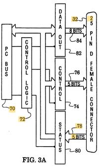
In the standard IBM XT configuration depicted in FIG. 3A, the PC bus [70] is internally connected through control logic [72] to a set of control latches [74]. Five bit lines [76] connect the unidirectional out control latches [74] to pins on the connector [32]. Five additional pins on the connector [32] connect via five status lines [78] to unidirectional in status latches [80] and then to the control logic [72]. Most significantly in FIG. 3A, note that a set of eight unidirectional out data latches [82] connect the bus [70] through lines [84] to pins on the connector [32]. The data latches [82] are unidirectional out to connector [32] and do not allow for reading data from the connector [32] back into the PC bus [70] via the data lines [84]. As will be seen hereinafter, in accordance with the present invention, the five status lines [78] are used by the network adapter [10] for reading data in to the PC bus [70], four bits at a time. This data transfer mode will hereinafter sometimes be referred to as a double quasi nibble transfer mode.
AT Parallel
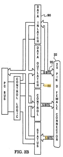
The IBM AT parallel port configuration depicted in FIG. 3B differs from the XT configuration in that it includes eight data out-latches [88] and eight data in-latches [90] both connected to the eight data lines [92]. The AT parallel port was designed only with data output capability in mind with a readback capability, i.e. via data in-latches [90], for detecting faults. The data out-latches [88] are not tristatable, i.e. they are always driving out. In operating with the AT configuration of FIG. 3B, the network adapter [10] is able to force the data out-latch [88] to all ones and is able to read data in, eight bits in parallel, via the data in-latch [90], because of its TTL implementation which allows a TTL ground to overcome a TTL high level. In summary, when properly driven, the AT parallel port inherently allows data bytes to move bidirectionally without any control of the bidirectionality.
PS/2 Parallel
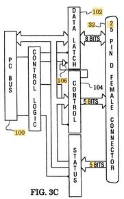
In the PS/2 parallel port configuration depicted in FIG. 3C, the PC bus [100] is connected through a bidirectional data latch [102] to the parallel port connector [32]. In this configuration, a bit within the control latch [104] controls the directionality of the data latch [102] via gate [106]. A network adapter [10] in accordance with the present invention sets the bit in the control latch [104] to set the directionality of the data latch [102], that is to either transfer data into or out of the data latch [102] with respect to the connector [32].
Thus, in summary, a standard XT parallel port (FIG. 3A) is strictly unidirectional, standard AT parallel port (FIG. 3B) was designed to be unidirectional but as a consequence of it being able to detect faults, can be used in a bidirectional fashion, and a standard PS/2 parallel port (FIG. 3C), is truly bidirectional and its directionality is controlled by a control bit.