Using Bidirectional
Parallel Printer Ports
Using Bidirectional Parallel Printer Ports
By Michael A. Covington
MicroComputer Journal 1995 Nov Dec, pages 34-37 physical
NOTE: In an effort to better understand the PS/2 Bidirectional parallel ports, I have searched for period articles describing them. In this case, I am not sure if and why the author thinks the Model 50 port can't be set to Bidirectional. This article seems to reference the "Type 1" parallel port. YMMD, LFO
How to exploit bidirectional lines if your parallel printer port has them
Many newer PCs, especially laptops, have bidirectional parallel printer ports that can read as well as write the eight data lines. As a result, the parallel printer port can be used like the bus of an eight-bit microprocessor to send data in both directions, and it interfaces nicely with numerous eight-bit devices. Jan Axelson's recent articles in Microcomputer Journal have explored in detail how to use the standard features that all parallel printer ports have in common. In this article, I'll tell you how to exploit bidirectional data lines if you have them.
To avoid misunderstanding, keep in mind that you can transmit data bidirectionally without using a bidirectional parallel port, as long as you do your input somewhere other than the eight data lines. Thus, for example, Eddie McMullen's printer-port voltmeter (MCJ, March/April 1994) doesn't require a bidirectional parallel port. "Bidirectional" means that the data lines, not just the status and control signals, are capable of input.
Data-Line Input
To take input through the data lines of the parallel port, you have to do three things: enable bidirectionality, switch the port into read mode and read the data.
Enabling bidirectionality is the difficult part. Bidirectional ports aren't bidirectional unless you explicitly set them up to be. This is to keep older software from accidentally putting the port into read mode by mistake. To make the parallel port bidirectional, you set a jumper (on most newer multifunction I/O cards) or run a setup program (on Toshiba and Zenith laptops, among others).
On an IBM PS/2 (Model 50 or greater), the only way to enable bidirectionality on the built-in parallel port is to run the special PS2BIDIR-.BAS program given in Listing 1. This program uses the PS/2's Programmable Option Select (POS) facility to make the parallel port bidirectional. Its effect lasts until you re-boot your computer. With after-market PS/2 parallel ports, you have it easier because you can generally select bidirectional mode in the setup program on the Reference Diskette.
Listing 1: QBASIC Program to Enable PS/2 Bidirectional Parallel Port
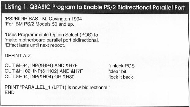
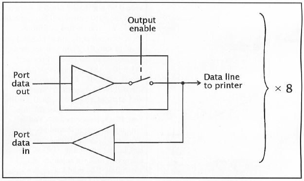
Fig1. All PC printer ports can read back their own output. Bidirectional ones can disconnect the output driver to accept Input.
Listing 2. Program Display All Parallel Printer-Port Bits
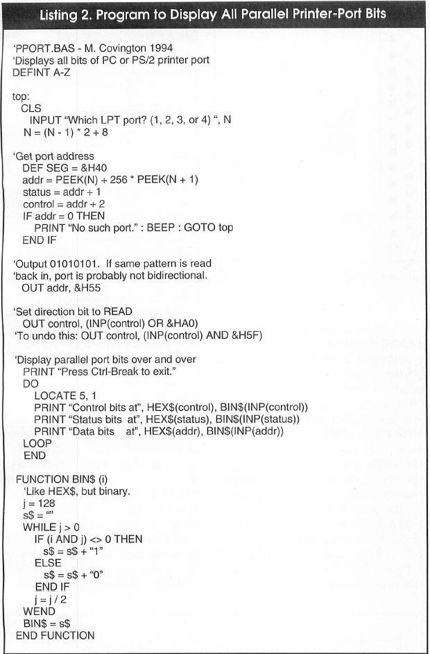
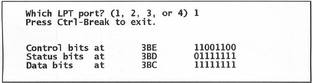
Fig. 2. Output of PPORT.BAS is this continuously updated display
With bidirectionality enabled, the port is still an output device and still drives a printer in the usual way until you switch it into read mode by setting Bit 5 or 7 in the control register. There's no harm in setting both bits.
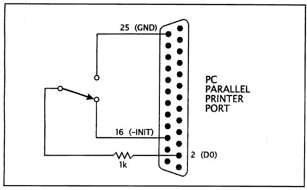
Fig 3. Simple demonstration of input through a parallel-port data line. -INIT line is normally high (+5 volts).
Some computers use one and some use the other. In BASIC, the instruction to do this is:
OUT control, INP(control) OR &HA0
where control is the address of the control register (the parallel port base address plus 2). For example, if the port is at hex 0378, control will be hex 037A. To get back into write mode, key in:
OUT control, INP(control) AND &H5F
Implementing Bidirectionality
Illustrated in Fig. 1 is how bidirectionality is implemented. All parallel printer ports have the ability to read back the data that's output to them. The original IBM PC used this feature for testing. The only thing new in a bidirectional port is the ability to disconnect the output from the data line, while the read-back inputs remain connected. You can read these TTL compatible inputs by taking input from the base address of the parallel port as follows:
result = INP(addr)
where addr is hex 037C, 0378, or 0278, as the case may be. The data bits aren't inverted. Each is 0 if low and 1 if high. Disconnected pins usually read as 1 but may pick up random noise if your parallel port uses CMOS or NMOS technology.
If the port is still in write mode and you try to read it, you'll get back whatever data was last written to it. You can exploit this fact to test whether a printer port is really bidirectional by writing a distinctive bit pattern to it (not 11111111 or 00000000, which might correspond to disconnected pins), switch the port to read mode (or try to) and see if you get the same bit pattern when you read it. If you do, the port is almost certainly not bidirectional, or at least isn't really in read mode.
PPORT.BAS Listing 2 is a program that puts all this together. Figure 2 shows how it displays all the bits of all three parallel-port registers. To demonstrate that a port is bidirectional, use the circuit in Fig. 3. The lowest data bit should toggle back and forth as you flip the switch. The 1,000-ohm resistor protects the parallel port against shorted outputs in case it turns out not to be in read mode when you perform the test.
Listing 3: Program to Read Data From Analog-to-Digital Converter
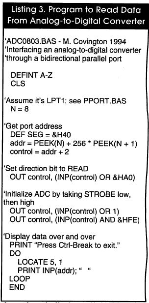
Fig. 4. General scheme for interfacing to bidirectional parallel port. Resistors protect ICs when both devices are in output mode.
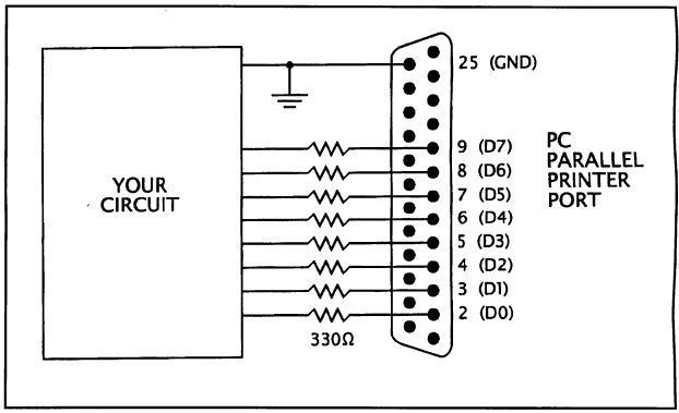
Figure 4 shows how to approach interfacing. Protective resistors are required because the parallel printer port is an output device from the moment your computer boots up until you put it into read mode, yet is connected to the outputs of your external equipment. Shorting outputs to each other can easily damage logic ICs unless current is limited to a safe level.
The 330-ohm resistors pass TTL level signals transparently but limit current to 10 mA when a low output gets shorted to a high output, or vice versa. This is a good use for the 330-ohm resistor packs that once were used as terminators on diskette drives. If your parallel port has MOS inputs (most bidirectional ones do) and you're using the data lines for only input, not output, you can usually get away with much larger-value resistors for added safety.
Interfacing
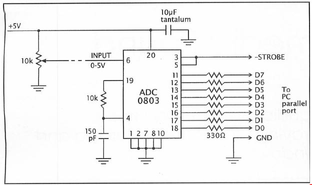
Shown in Fig. 5 is a practical interfacing setup. An ADC0803 analog-to-digital (A/D) converter reads its input voltage (0 to +5 volts) as a value from 0 to 255. ADC0803.BAS Listing 4 is a program that accepts the input and displays it. The eight data lines carry the data, through 330-ohm protective resistors. The strobe line is used to reset the ADC so that it will start running at the beginning of a session. No protective resistor is needed because, unlike the data lines, the strobe line isn't a TTL totem-pole output. It's open-collector, with a 4,700-ohm pull-up resistor, and can't drive excessive current into the ADC.
Fig. 5. Designed for eight-bit microprocessor bus, ADC0803A/D converter interfaces equally well to bidirectional parallel port. ADC0801, 0802, 0804 and 0805 work in this circuit. Potentiometer varies input voltage for testing purposes
Finally, a word about "brute-force bidirectionality." Some experimenters have found that a standard (unidirectional) PC parallel port can work bidirectionally if driven by a circuit that can sink a lot of current (like 20 mA) in the low state. The technique is to write all 1s to the base address of the port and then pull some of the data lines low and read the data back in. Sure enough, the lines that are pulled low read back in as 0, not 1. But this technique risks overheating the output chip (originally a 74LS374, nowadays often a special NMOS or CMOS LSI circuit). [NOTE: a XIRCOM patent mentions this "forcing" with use of the Pocket adapters on older IBM PCs, maybe early PS/2s LFO]
A better technique, if you have an original IBM parallel port or close equivalent, is to find Bit 5 of the control register (it's decoded at the output of a 74LS174 but never used) and route it to the output-enable pin of the 74LS374 that drives the data lines. This will require a bit of circuit tracing and shouldn't be done blindly.
The alternative is to just buy an I/O card that includes a new-style bidirectional parallel port. Be wary of connecting experimental circuits to your main I/O card if it includes disk controllers and other vital parts of your PC. Such ports are very vulnerable to static damage, and when zapped, they crash the whole computer.