Auxiliary Video
Connector Signals
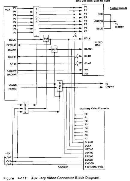
Auxiliary Video Extension Circuit
NOTE: "Buffers" are Tri-State Buffers?
My question is are the buffers Bi-Directional, see the little "o" where the control line attaches to the buffer?
The auxiliary video connector is a 20-pin connector located in-line with one of the channel connectors on the system board. This connector allows video data to be passed to and from an adapter. The base video buffers can be turned off, and video output from the adapter can be sent through the video DAC to the display connector. The full [micro] channel is available for use by the adapter.
Video output can be passed in only one direction at a time. The 'dot clock' signal
cannot drive both EXTCLK to the VGA and PCLK to the DAC.
Note: The video extension supports only the VGA function
Note: Some Video Subsystems drive VGA video at video rates higher than those specified here. This is done to achieve higher screen refresh rates and better front of Screen quality (less flicker).
When this is the case, the Video Extension will be disabled and will not available for use.
Auxiliary Video Extension Signal Descriptions
VSYNC: Vertical Synchronization: This signal is the vertical synchronization signal to the display. Also see the ESYNC description.
HSYNC: Horizontal Synchronization: This signal is the horizontal synchronization signal to the display. Also see the ESYNC description.
BLANK: Blanking Signal: This signal is connected to the BLANK input of the video DAC. When active (0 Vdc), this signal tells the DAC to drive its analog color outputs to 0 Vdc. Also see the ESYNC description.
P7· P0: Palette Bits: These eight signals contain video information and comprise the PEL address inputs to the video DAC. See also the EVIDEO description.
DCLK: Dot Clock: This signal is the PEL clock used by the DAC to latch the digital video signals, P7 through P0. The signals are latched into the DAC on the rising edge of DCLK.
This signal is driven through the EXTCLK input to the VGA when DCLK is driven by the adapter. If an adapter is providing the clock, it must also provide the video data to the DAC. Also see the EDCLK description.
ESYNC: External Synchronization: This signal is the output-enable signal for the buffer that drives BLANK, VSYNC, and HSYNC. ESYNC is tied to + 5 Vdc through a pull-up resistor. When ESYNC is high, the VGA drives BLANK, VSYNC, and HSYNC. When ESYNC is pulled low, the adapter drives BLANK, VSYNC, and HSYNC.
EVIDEO: External Video: This signal is the output-enable signal for the buffer that drives P7 through P0. EVIDEO is tied to + 5 Vdc through a pull-up resistor. When EVIDEO is high, the VGA drives P7 through P0. When it is pulled low, the adapter drives P7 through P0.
EDCLK: External Dot Clock: This signal is the output-enable signal for the buffer that drives DCLK. EDCLK is tied to + 5 Vdc through a pull-up resistor.
When EDCLK is high, the VGA is the source of DCLK to the DAC and the adapter. The Miscellaneous Output register (see "System Board I/O Controllers") should not select clock source 2 (010 binary) when EDCLK is high.
When EDCLK is pulled low, the adapter drives DCLK. If the adapter is driving the clock, it must also provide the video data to the DAC, and the Miscellaneous Output register must select clock source 2 (010 binary).