Token Ring FDX
All of the IBM Micro Channel engineering documents are
tucked away in the third level underground vault of a
decrepit building in Raleigh, NC. The vault door was
thermite welded shut, then covered with a grid of welded
rebar, sprayed over with ShotCrete, then drywalled. The
workers were spread to IBM offices around the globe, then
systematically disappeared. So don't ask questions you don't
want to know the answers to. -LFO"The Hunt for Blue FDX" is an adaptation of the Tom Clancey novel. Or, the more mundane story...
Token-ring migration to switched LAN interconnect 1997 [Internet Archive]
David Beem was puttering around with a CISCO 3845, and he had a NM-1E1R2W Network Module that he wandted to hook up a 4Mb T/R adapter to [obviously using a MAU]. I whipped out my NM-1FE1R2W [working copy NM-1FE1R2W] to compare to it, then that brought up a question: "What is required for FDX (and DTR)"? Things started out by comparing chipsets, then czeching the FDX status of various IBM Streamer family adapters. In addition, it seems quite possumble that IBM used these same FDX capable chips in the 82nn NWAYS network equipment [of which I lack ANY chip identification].
IBM chipset on NM-1E1R2W
Top - 38H6818 (bad image, unsure) PCI Busmaster chip?
50G7028 Tolkien Ring front end
38H6302 Multi-Protocol Chip (MPC) contains a Token Ring and Ethernet MAC
Adapters identified by IBM as having FDX capability:
Token-Ring Adapter FDX Drivers/Microcode via Internet Archive
Token Ring Adapter
Auto 16/4 MC - Early pages say 1997, then "Contact IBM for more information"
NOTE: It MIGHT be possumble. I dunno. -LFO
10H4710
50G7028 Token Ring front end
Auto LANStreamer MC32 - Released
73G2692 or 38H6302 Multi-Protocol Chip (MPC)
50G7028 Token Ring front end
Dual LANStreamer MC32 - Released
73G2692 Multi-Protocol Chip (MPC)
50G7028 Token Ring front end
LANStreamer MC16 - No FDX
50G8180 Token Ring protocol chip "Huntingdale".
National Semiconductor 93F2932 Token Ring front end
LANStreamer MC32 - No FDX
50G8180 Token Ring protocol chip "Huntingdale".
National Semiconductor 93F2932 Token Ring front end
Ethernet FDX capable adapters
EtherStreamer MC 32
60G0663 or 73G2692 Multi-Protocol Chip (MPC)
National Semiconductor DPADP10 Ethernet front end [no documents :( ]
Dual EtherStreamer MC 32
73G2692 Multi-Protocol Chip (MPC)
National Semiconductor DPADP10 Ethernet front end [no documents :( ]
Full-Duplex Operation
In this paper, the classical operation mode of Ethernet and token ring is referred to as half-duplex (HDX), meaning that a station can either transmit or receive data but not both simultaneously. Also, in the shared LANs, only one station can transmit at a time. A server with a single network interface connection (NIC) is limited to the amount of bandwidth that it can acquire in a shared-network environment as network loading increases. Priority access schemes in both token-ring and FDDI systems can reduce access delays for selected stations, thus making them well suited for many types of multimedia applications.
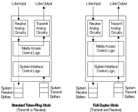
FDX is a well-known mode of operation in communication networks. However, it is only with recent advances in switching technology that it is now practical to consider switching and FDX operation at speeds of 10, 16, or even 100 Mbps. In FDX operation, separate transmit and receive paths are dedicated on a point-to-point link rather than repeating the incoming data signals (See Figure 3).
Figure 3: Full-Duplex Adapter Operation

There are no collisions or tokens to regulate media access, because dedicated transmit and receive paths exist. Each station simply transmits data once it has been correctly formatted within the adapter. This greatly simplifies the MAC protocol (Reference 3). The switch and adapter designs ensure that there are adequate buffers to receive the incoming frames. Data loss can occur during periods of bursty traffic if inadequate buffer capacity is provided (Reference 4). Some limited flow-control schemes were designed for the connection-oriented link-level protocols for relieving congestion in intermediate bridges and are also applicable to switched environments. The best example is the dynamic-window algorithm defined for IEEE 802.2 Type 2 (connection-oriented) service (Reference 5).
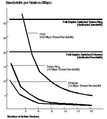
Figure 4: Dedicated FDX vs Shared-Bandwidth Performance

The most compelling reason to migrate to FDX operation and a switched environment is the significant gain in bandwidth that is available to each individual station (References 3 and 6). With shared networks, such as token ring and Ethernet, the amount of bandwidth available to each station decreases in proportion to the number of stations that share the link (See Figure 4). This has been sufficient for the past 10 years due to the limited bandwidth requirements of existing applications. However, emerging multimedia applications could require as much as 4 to 6 Mbps per session. This bandwidth can be provided by simply dedicating to each station the full bandwidth of the LAN adapter. However, once the link has been dedicated to one station, FDX operation then essentially doubles the available bandwidth while also decreasing end-to-end latency.
References
1. McQuillan, J., "The End of Shared-Medium LANs," Business Communications Review, October 1992.
2. Amer, K., "Migration to Switched Ethernet LANs-- A Technical White Paper," February, 1995, available from the Mechanicsburg Distribution Center, Form Number G224-4432.
3. Christensen, K., Noel, F., and Strole, N., "Emerging Trends: Full-Duplex and the Switched LAN," Proceedings of 19th Conference on Local Computer Networks, October 1994, 242-248.
4. Saunders, S., "Traffic Jam at the LAN Switch," Data Communications, 21 November 1994, 53-58.
5. Bux, W. and Grillo, D., "Flow Control in LANs of Interconnected Token Rings," IEEE Transactions on Communications, COM-33 (October 1985), 1058-1066.
6. Tolly, K., "Token Ring Switching: The Design Challenge," Data Communications, February 1995, 97-104.