ITBU Installation Kit
IBM PS/2
Internal Tape Backup Unit Option Diskette ver 1.01
64F7467 IMA formatIBM PS/2 ITBU Installation and Testing Instructions ver C [ver B similar]
ITBU Brochure
NOTE: Being pedantic [like our missing WBST], IBM also referred to the bezels as "Tape Cover Plates". Hope that makes you feel complete...
NOTE: Thanx to Lorenzo Mollicone for providing me with a NOS Kit C.
188-148 IBM PS/2 ITBU - ITBU Drive, 50 / 70 and 60 / 80 Bezels
190-051 IBM PS/2 ITBU Installation Kit A - 65 / 8580 Bezels
190-181 IBM PS/2 ITBU Installation Kit B 60 / 65 / 80 / 90 / 95 Bezels
191-093 IBM PS/2 ITBU Installation Kit C 40 / 60 / 65 / 80 / 90 / 95 Bezels
193-126 IBM ITBU Installation Kit D [ HINT - NO "PS/2" in title! ]
NOTE: Used in: VP 6382, 6384, 6387, PS/1 2155, EduQuest 9603, 9604, 9605
IBM PS/2 ITBU Installation Kit C Tray
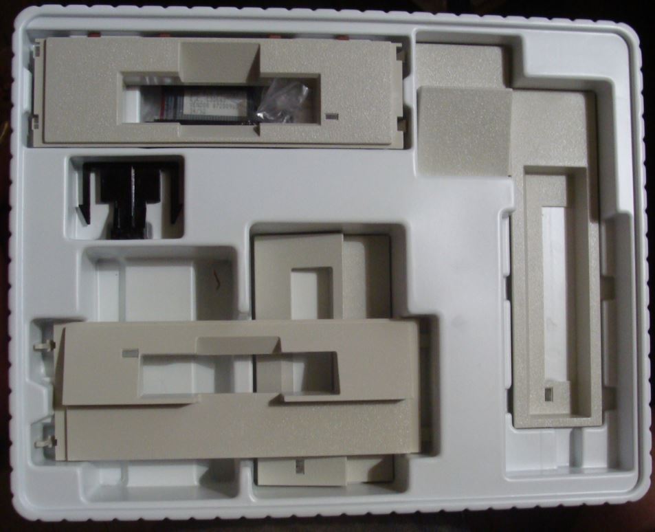
Bezels and adapters in order, clockwise, starting at upper left corner:
64F3189 Model 40 / 57 / 77 Bezel "2"
34F2717 Adapter Cable [34 to 40 pin cable] [Partly visible inside 64F3189]
33F5961 Model 90 Bay D filler Bezel "3"
33F8279 / 33F8277 Model 56 / 76 "3" [my best SWAG]
34F2721 Model 85 / 95 5.25" Bay Bezel "1" [on top]
33F6031 Model 60 / 65SX / 70 / 80 Bezel "3" [below 34F2721]
APB ??? Mounting Clip for Model 40 / 57 / 77 [black plastic]
92F3762 Stop Clip Bay 3 of 8557, 9557, 9577 and Bay 2 of 9556 and 9576
IBM PS/2 ITBU Installation Kit C Box
ITBU Bezels List for all Kits:
You will notice numbers in quotes, I think IBM originally gave single digit part numbers to each bezel and associated them to specific systems. My SWAG is that IBM quit bothering adding a specific single digit part number and just used the common seven character P/N.
30F5161 Model 50 / 50z / 70
30F5163 Model 60 / 65 / 80
33F6031 Model 60 / 65 / 70 / 80 Bezel "3"
33F5961 Model 90 Bay D filler Bezel "3"
34F2721 Model 85 / 95 5.25" Bay Bezel "1"
64F3189 Model 40 / 57 / 77 Bezel "2"
33F8279 / 33F8277 Model 56 / 76 "3"
34F2717 Adapter Cable [34-pin edgecard to 40 pin cable]
APB ??? Mounting Clip for Model 40 / 57 / 77 [or "Stop Clip" ? ]
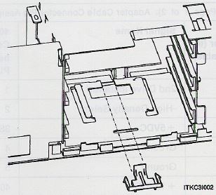
Mounting Clip for Model 40 / 57 / 77
"If you are using cover plate number 2, you must install the Mounting Clip in the rear of Bay 3 (Lower Left Bay) with the tab facing up."
 |
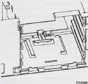 |
Look at the bottom center of the 40 / 57 / 77 drives bay, notice the "lips" on each side of the Mounting Clip? The ITBU Slide slips over the "Lips".
Though the Install manual refers to it as the "Mounting Clip", it might very well be a "Stop Clip" to prevent the ITBU from being pushed back into the case.
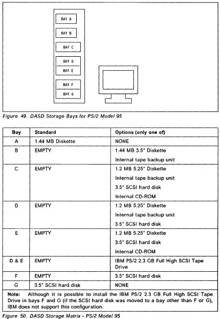
The ITBU drive comes mounted on a "Slide", think of the 95 floppy mount, or the Model 70 floppy mount. Since there is a 5.25" bay bezel for the Model 85 / 95, you should be able to mount the ITBU in a Tray [metal frame 3.5" to 5.25"].
NOTE: IBM thought the ITBU could be mounted in the Model 90 in Bay B and D, and in the Model 95, Bay B. Maybe the Model 95 Bay B info was just a mistake? The ITBU connects to the FDC, therefor it MUST fit into a floppy bay... I don't know.
The illustration says Bays B, C, and D. Sensible, the floppy cable is only so long.
GG24-3616-00 PS/2 Models 95, 90, 55 LS and P75 486 Fundamentals page 100
Confused over Tray, Slide, and Rails? No longer...
34F2717 Adapter Cable [34 to 40 pin cable]
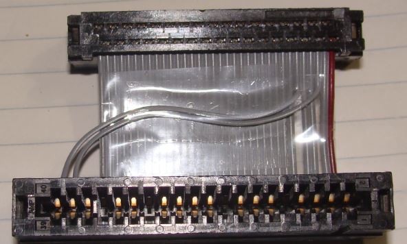
This is to adapt the 34-pin edgecard on the ITBU to a 40 pin floppy cable. I would be comfortable with this up to the systems that support the security and eject functions of Electronic Eject floppy drives. The EE floppy drives have to redefine some signals in order to support the security and eject functions.
Adapter Cable Connector Pin Assignments
NOTE: The adapter connects pin-for-pin the 34-pin connector to the 40-pin connector EXCEPT 34 pin 03 goes to 40 pin 38, 34 pin 06 goes to 40 pin 40.
| 34 Pin |
Signal Name |
40 Pin |
| 01 |
2nd Drive Installed |
01 |
| 02 |
-High Density Select |
02 |
| 03 |
+5Vdc |
38 |
| 04 |
Ground |
04 |
| 05 |
Ground |
05 |
| 06 |
+12Vdc |
40 |
| 07 |
Signal Ground |
07 |
| 08 |
-Index |
08 |
| 09 |
(No Connection) |
09 |
| 10 |
-Motor Enable 0 |
10 |
| 11 |
Signal Ground |
11 |
| 12 |
-Drive Select 1 |
12 |
| 13 |
Ground |
13 |
| 14 |
-Drive Select 0 |
14 |
| 15 |
Signal Ground |
15 |
| 16 |
-Motor Enable 1 |
16 |
| 17 |
(No Connection) | 17 |
| 18 |
-Direction |
18 |
| 19 |
Signal Ground | 19 |
| 20 |
-Step |
20 |
| 21 |
Signal Ground | 21 |
| 22 |
-Write Data |
22 |
| 23 |
Signal Ground | 23 |
| 24 |
-Write Enable |
24 |
| 25 |
Signal Ground | 25 |
| 26 |
-Busy |
26 |
| 27 |
(No Connection) | 27 |
| 28 |
-Write Protect |
28 |
| 29 |
Signal Ground | 29 |
| 30 |
-Read Data |
30 |
| 31 |
Signal Ground |
31 |
| 32 |
-Head Select 1 |
32 |
| 33 |
(No Connection) | 33 |
| 34 |
-Ready |
34 |
| 35 |
||
| 36 |
||
| 37 |
||
| 03 |
Already at top of table |
38 |
| 39 |
||
| 06 |
Already at top of table | 40 |