SYSGEN Bridge File
SYSGEN
Bridge-File Owner's Manual Nov 1991SYSGEN Bridge-File software, ver 3.44
SWAG - These adapters plug directly into the system board or planar floppy connector. There is no need for an ADF. However, after installing a Bridge File and adding another floppy, you will have to run System Configuration again [SC.EXE].
If you need the full configuration, refer to the Owner's Manual.
Bridge-File Host Adapter
| PC/AT | 1030-AT | 2294-01 |
| 25/25 286 | 1030-PS/2 | 2293-01 |
| 30/30 286 | 1030-PS/2 | 2293-01 |
| 50/50Z | 1050 | 2295-01 |
| 55SX | 1055 | 3390-01 |
| 60/65/80 | 1060X | 2296-65 |
| 70 | 1070 | 2297-01 |
| 90/95 | 1090 | 7450-01 |
PSA1030 [AT -OR- PS/2 !!!]
NOTE: The version of the 1030 adapter designed for PC/AT use contains different signal routing from the version designed for the PS/2 Models. Do not interchange these two adapters; always use the part number that applies to your equipment.
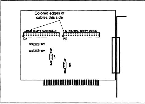
The 1030 Adapter
Two different variations of the 1030 adapter exist:
1030-AT: For IBM PC/AT computers. 34-pin connectors at JAD and JCA
1030-PS/2: For Models 25, 25-286, 30, 30-286. 40-pin connectors at JAD and JCA
1030 Adapter Connections
Three components are connected by ribbon cables. The 1030 Adapter, the diskette drive Controller, and either one or two diskette Drives. The controller is usually a circuit board which plugs into the computer's PC-bus, but sometimes (as in the PS/2 Model 30 and in some compatibles) it is built into the computer's motherboard.
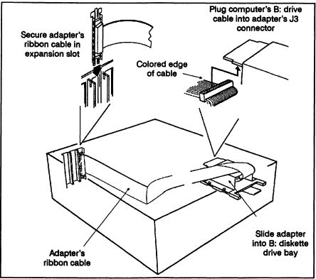
Connector JAD connects the Adapter to the Drives. In most installations, the ribbon cable that normally connects the drives to the controller is used for this. An exception is the IBM PS/2 Model 30; this installation requires a separate cable (called the A/D cable, Adapter and Drives) because the ribbon cable that comes with the computer won't reach all the way to where the 1030 adapter is installed.
Connector JCA connects the Controller to the Adapter. This cable (called the C/A cable, Controller and Adapter) is supplied with all 1030 adapters.
Jumper Positions for the 1030 Adapter
W1 (Address Select): This address jumper selection is factory set to correspond to the equipment that the adapter will be installed in:
• PS/2 Model 30: 372 hex
• PC/AT: 3F2 hex
W2, W5 (External Power): The 1030 adapter is factory set to operate from the host computer's internal power supply. If you are installing an external power supply on a Bridge product that uses the 1030 adapter, jumpers W2 and W5 must be removed from the 1030 adapter. If you are using a Bridge-Tape unit with a PS/2 Model 30 286, you must use an external power supply.
WARNING! Failure to remove the W2 and W5 jumpers before an external power supply is connected can result in damage to both the Bridge product and the computer.
W6 (Density Line Inversion): If the 1030 adapter is in a PC/AT computer, this jumper should be in the upper (AT position. If you installing the 1030 adapter in a PS/2 computer, this jumper should be in the lower (PS/2) position.
WARNING! The 1030 adapters for the PS/2 Model 30 and the PC/AT are not interchangeable. Do not attempt to use these adapters in any system but the one they were designed for.
1030-PS/2 Adapter in Model 25, 25 286, 30 or 30 286
1. Jumper W6 on the 1030 adapter to the PS/2 position.
2. Jumper W1 on the 1030 adapter to the 372 position.
3. Jumper W2 and W5, unless Bridge-File is connected to auxiliary power supply.
4. The adapter is installed correctly.
PSA1050
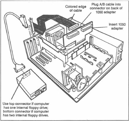
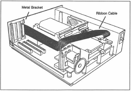
The 1050 adapter replaces the 8550's drive riser. It attaches the diskette drives to the floppy disk controller on the computer's motherboard. The 1050 also has a connector for external drives. Signals are passed from this connector to another connector mounted on a bracket at the back of the computer by a cable called the A/B (for Adapter to Bracket) cable.
The 1050 adapter simply replaces the computer's standard diskette drive connection card, the A/B cable is connected to the 1050 adapter, and the A/B cable's bracket is secured at the back of the computer.
Jumper Positions for the 1050 Adapter
W1-W3 (Disk/Tape selection): These jumpers should always be set towards the center of the board (the disk position). The illustration shows the location of the 1050 adapter's jumpers.
1050 Adapter in Model 50 or 50Z
1. Jumpers on the 1050 adapter are set nearest the white DISK marking.
2. The adapter is installed correctly.
1055 55SX / LS
NOTE: The 1055 adapter has a 44-position connector to fit the Model 55's 40-pin header. The extra 4 positions help to center the connector.
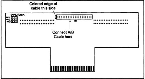
The 1055 Adapter
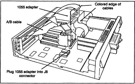
The 1055 mounts vertically into connector J8 on the Model 55 motherboard.
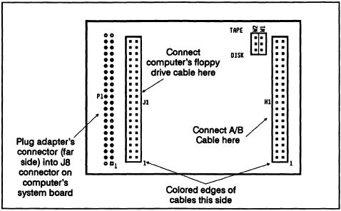
The floppy disk interface cable that is normally plugged into J8 gets plugged onto connector J1 of the 1055 adapter. A second connector on the 1055 adapter, H1, is used by the A/B Cable, which routes signals for one or two external drives to a connector secured at the back of the computer.
Since the Model 55 computer always comes with only one internal 3.5-inch floppy drive, the 1055 adapter will only be able to support two external drives, giving a total of three.
Jumper Positions for the 1055 Adapter
W1 - W2 (Disk/Tape selection): These jumpers should always be set toward the middle of the board (the disk position).
W3 - W4 (+5V & +12V): These are normally jumpered to allow +5V and +12V to power external floppy or tape drives from the internal power supply of the computer. If other cards plugged into the system excessively load down the internal power supply, remove W3/W4 and use a SYSGEN external power supply to power the external drives.
1055 Adapter in Model 55 SX/LS
1. Jumpers on the 1055 adapter are set nearest the white DISK marking.
2. The adapter is installed correctly.
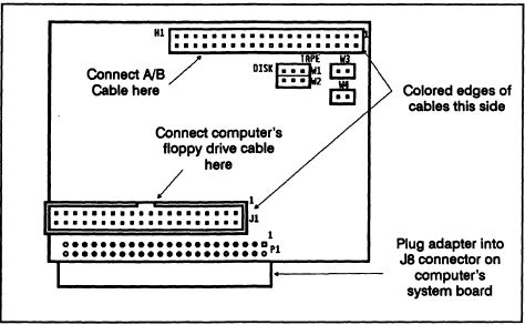
1060 Adapter [60, 65SX, 80]
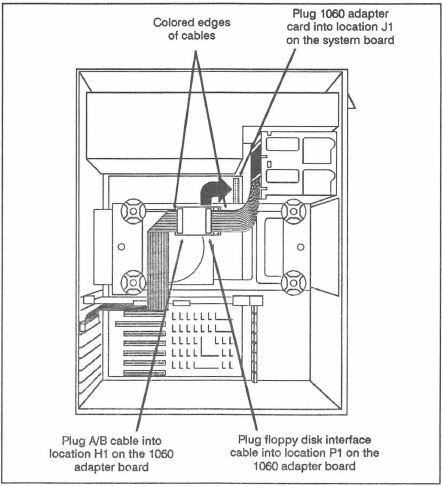
The 1060 plugs into connector J1 on the Model 60/65SX/80 computer. The floppy disk interface cable, which normally is connected to J1, is then connected to a connector on the 1060 adapter. A second connector on the 1060 adapter, H1, is used by the A/B Cable, which routes signals for an external diskette drive to a connector secured at the back of the computer.
Jumper Positions for the 1060 Adapter
W1-W2 (Disk/Tape selection): Both jumpers should always be set towards the center of the board (the disk position).
1060 Adapter in Model 60, 65, or 80
1. Jumpers on the 1060 adapter are set nearest the white DISK marking.
2. The adapter is installed correctly.
PSA1070
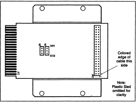
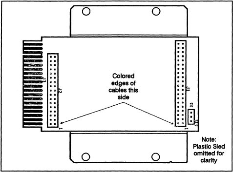
The 1070 adapter is mounted on a sled and inserts into the right internal 3.5-inch floppy slot on the PS/2 Model 70 computer. An attached cable is routed to the back of the computer for external disk drive installation. The illustration shows the board with the sled removed.
Jumper Positions for the 1070 Adapter
W1-W2 (Disk/Tape selection): Both jumpers should always be set towards the outer silkscreen marking (the disk position).
1070 Adapter in Model 70
1. Jumpers on the 1070 adapter are set nearest the white DISK marking.
2. The adapter is installed correctly.
PSA1090
The 1090 adapter is mounted on a sled and inserts into the right internal 3.5-inch floppy slot on the PS/2 Model 90 computer, or the lower 3.5-inch floppy slot on the Model 95. An attached cable is routed to the back of the computer for external disk drive installation. The illustration shows the board with the sled removed.
Jumper positions for the 1090 adapter
W1 (3.5/5.25 selection): This jumper should be set towards the "3.5" marking when a 3.5-inch Bridge-File is installed, and towards the "5.25" marking when a 5.25-inch Bridge-File is installed.
When connecting two bridge-Files to the 1090 adapter, jumper W1 must be set to the drive type of the first Bridge-File in the chain (B:).
1090 Adapter in Model 90 or 95
1. Jumper on the 1090 adapter is set nearest the white 5.25 marking if used with a Bridge-File 5.25, or nearest the white 3.5 marking if used with a Bridge-File 3.5.
2. The adapter is installed correctly.