Ethernet Controller Adds
Communications To SCSI Bus
Electronics Design, Sept 8, 1988 pages 91-96
by TOMAS RUSS
"Originally a disk control protocol, the SCSI bus standard offers several advantages to users of LANs."
References:
1. ANSI, Small Computer System Interface (SCSI), X3.131-1986.
2. Western Digital, WD33C93 Data Sheet.
3. National Semiconductor, Advanced Peripherals, IEEE-802.3, Local Area Network Guide.
4. Hitachi, HD64180 User's Guide, 1985.
Putting an Ethernet controller on the Small Computer System Interface (SCSI) bus offers some powerful advantages. For one, it lets a user connect an Ethernet node to any computer that supports SCSI, which today means almost all of them-from PCs to VAXs. It also reduces cost by integrating the transceiver on the same card with the controller. And because the SCSI bus can extend 6 m (18 ft) with a single-ended drive and 25 m (75 ft) with a differential drive, the controller can be outside the computer cabinet, directly connected to the Ethernet coaxial cable through the 50-conductor SCSI cable.
Also, the bus accommodates local intelligence and multithreaded logical connections. These features benefit software designers because they let the Ethernet controller pick up some of the higher levels in the ISO / OSI model, at least up to the transport layer. This ability not only offloads the host, but also avoids the inherently useless process of copying packets from one place to another until the proper program can interpret them.
Some computers, such as the Macintosh, have SCSI capability built in. For systems that already have SCSI based storage devices, a user just adds the Ethernet controller at the end of the bus. Those without this head start must add a SCSI host adapter.
The controller's simple hardware design, using 17 DIP devices and several passive components, keeps the 8-bit processing that's natural for Ethernet and SCSI throughout the board. Three main ICs a SCSI controller, an Ethernet controller, and a high-integration 8-bit processor are at the heart of the design. A shared local bus lets the memory access all three chips (Fig. 1).
Fig 1: ETHERNET CONTROLLER CIRCUIT

1. THE ETHERNET CONTROLLER section maintains the 8-bit architecture natural to both Ethernet and SCSI. A shared local bus offers memory access to the circuit's three main ICs: a SCSI controller (WD33C93), an Ethernet controller (DP8390), and a highly integrated 8-bit processor (HD64180).
Even though billed as a general purpose interface, the SCSI standard shows its origins as a disk-controller protocol as soon as designers try to use it for something else. [1] The bus's inherent master/slave architecture implies that the host computer always "knows" what the peripheral is doing. As a result, the asynchronous events typically found in communication controllers are difficult to flag.
A good example is the sequence of events in an elementary read command initiated by the host computer. If the peripheral is a disk drive, sooner or later the correct track and sector are found, and the information is retrieved and delivered to the host. This read operation is completed in a known period, normally the disk-access time.
This is not the case when the SCSI target is a communication controller. In the example noted, if the host requests a read from the Ethernet controller, it won't get its data back until the packet arrives, which can well be a very long time (imagine a computer waiting for a remote user to press a key on a terminal). In the meantime, if the same host wants to. write a packet through the Ethernet, it has no way, short of a full-blown reset, to break the previous connection on the read.
There are two ways out of this deadlock. First, a designer can give the peripheral the ability to act as a "host" ("initiator" in SCSI terminology) and give "peripheral" ("target" in SCSI) capability to the host. Then the system can flag asynchronous events from the controller to the host computer without a previous request. The problem with this scheme is that the host operating system must incorporate special drivers that make the host computer appear to be a target.
The preferred solution to the "wait for read" syndrome is to take advantage of SCSI's ability to maintain multiple logical connections through one physical path-that is, multithreading. With multithreading, the host (SCSI initiator) connects to a peripheral (target) and requests a certain transaction. If the peripheral isn't ready for the request, the physical path between the two devices is freed up, leaving the bus available for other transactions.
SCSI devices achieve multithreading with the logical unit number (LUN) concept. The controller accepts up to eight simultaneous host connections, called LUNs 0 to 7 (more could be employed through the SCSI extended identify mechanism). LUN 0 is a write and control channel (all such transactions execute in a limited time). LUNs 1 and up are read channels. As a result, a read request to LUN 1 can disconnect if no packet is waiting on the controller's receive buffer, so that write and control requests can proceed. LUNs 2 and up allow the controller to handle higher layer software. Consequently, each LUN represents an open socket or channel between the host and the outside world.
A total of 64 kbytes of static memory is used for buffering, and another 64 kbytes for program code and data. Two DMA channels, one in the processor and another in the Ethernet controller chip, speed data transfer. Careful priority analysis avoids lost data when more than one device wants control of the bus. One programmable logic device (PLD) supplies all decoding and DMA transaction timing.
At the SCSI end, the WD33C93 SCSI bus interface controller (SBIC) chip manages the traffic between the SCSI bus and the controller buffer memory. [2] This chip implements all low-level SCSI protocols in firmware, so very little work is left for the local microprocessor (HD64180). In a typical case, the designer programs the SCSI chip to wait for an initiator to select it and send a SCSI command. Only then is the processor alerted (through INT2) for further action.
Owing to the low byte count involved, SCSI commands are processed using programmed I/O access to the WD33C93. SCSI data, however, is transferred by a DMA controller in the HD64180. Because this DMA controller doesn't recognize
the typical REQ/ ACK handshake, the PLD is programmed to identify the DMA cycle and automatically generate the ACK signal for the SCSI chip. A SCSI DMA transaction from controller to host takes six clock cycles/byte (651 ns); a host-to controller transfer takes seven cycles/byte, or 760 ns (Fig. 2).
Fig 2: SCSI DATA TRANSFER TIMING
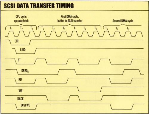
2. THE PLD GENERATES the DACK and WR signals to the SCSI bus interface
controller while the processor is still in the first read cycle. The second write cycle, to a nonexisting destination, is ignored, but it gives the SBIC time to lower its DREQ line and to obtain the next DMA cycle without releasing the bus. The PLD uses the Delayed Load Instruction Request (LIRD) and ST lines to tell between DMA and regular CPU cycles.
At the Ethernet end, the DP8390 Network Interface Controller (NIC) manages the Ethernet traffic and packet encapsulation/ decapsulation. [3] The chip supplies automatic address recognition and check sum insertion, which are normal in all Ethernet chip controllers, as well as buffer management.
Typically, the network interface controller raises the BREQ line to the HD64180 anytime the controller wants to retrieve a packet from or place a packet into the buffer memory. Once the bus is granted, the NIC uses its own DMA controller to effect the data transaction. The bus grant signal from the processor, -BACK, enables the 74ACT373 latch. The latch picks the DMA controller's low-byte address information, which is generated at the NIC's AD0-7 lines when the Address Strobe (ADS0) line is toggled.
The high-byte address information is generated independently on the NIC's A8-15 lines. When the operation is complete, the controller releases the bus and interrupts the processor for further action. Since the NIC has its own buffer manager for received packets, overhead is minimal. Each received packet is preceded by a NIC-generated header with the status, length, and a link pointer to the next received packet.
Because the NIC has higher priority for bus use than the processor does, the controller can never be denied access to the buffers when an Ethernet packet arrives and SCSI transactions are taking place. The bus is released in a maximum of five and a half processor clock cycles, or 600 ns, so the NIC's 16-byte FIFO buffer cannot be overrun.
Data transfers between the buffer memory and the NIC occur in 8-byte bursts. Each byte transfer takes 200 ns (four 20-MHz clock cycles), and the overhead for requesting the bus adds an average of 500 ns. This adds up to 2.1 μs per burst. On the other hand, Ethernet packets flow at 6.4 μs per 8-byte burst, which means that packet transfers over Ethernet consume only about a third of the available bus bandwidth. The rest is available for SCSI traffic from the host or for bookkeeping tasks by the local processor.
The controller's memory is composed of a 32-kbit-by-8 EPROM for program storage and three 32-kbx8 static RAMs, one for program data and two for packet buffering. One wait state is inserted on an EPROM access, owing to its longer access time and the shortened read cycle on the processor's op code fetch. Half of a 74ACT74 section and a NOR gate create the wait state.
Fig 3: TRANSCEIVER SECTION
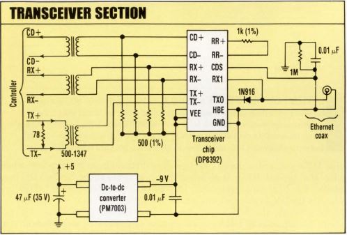
3. THE TRANSCEIVER STAGE needs only one IC. The entire controller-transceiver fits on a 6-by-4.5-in. circuit board.
From the NIC, packets are sent and received through the DP8391 Manchester encoder and the DP8392 transceiver chip (Fig. 3). A dc-dc converter and a transformer furnish galvanic isolation between the transceiver and controller sections.
As noted, the HD64180 processor, running at 9.2 MHz, has relatively little work to do. Once the SBIC and NIC are correctly programmed, the processor waits for interrupt calls from those two controller chips. But the processor does have two major tasks: managing the buffers and interpreting and executing the host commands sent through SCSl. [4]
Fig 4: DATA FLOW DIAGRAM
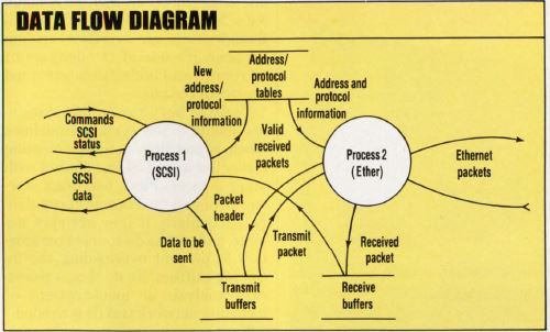
4. THE SOFTWARE'S top-level data-flow diagram includes two processes that handle SCSI and Ethernet requests. Interrupt signals from the respective controller chips activate the processes.
A software schematic in the form of a data-flow diagram explains how the HD64180 performs these tasks. Assume that the host wants to send data to a network destination. The host issues a SCSI write command, waking up Process 1-called "SCSI" (Fig. 4). This process sets up the DMA controller channel to download the data from the host into the Transmit Buffers area. When this transfer is finished, the host receives status information signaling the successful completion.
Process 1 then signals Process 2, "Ether," which adds the corresponding headers to the packet and transmits it. How much header information is added depends on the number of protocol layers implemented. Normally, the data link addresses (source and destination) are pulled from the Address/ Protocol Tables and incorporated in the packet. Also, the corresponding protocol identification is added to the Ethernet Type field for recognition by the receiving counterpart. Similarly, TCP and upper layer headers can be added to the packet.
When the packet is assembled and checked, the processor sends the NIC a set of pointers indicating where the packet is stored and asks the controller to send it. Ether then goes to sleep until the transmission is completed and an interrupt generated by the NIC reawakens the process. Depending on the protocol implemented, the packet just sent is either discarded or saved for a Receipt
Acknowledge by the receiving end. Either way, the SCSI status sense area is updated to show success or failure.
The transmit and receive buffers are organized as logical rings. Pointers are moved around by the processor and NIC after each transaction is concluded.
When it receives a multicast packet, the processor analyzes the packet's address and checks for a match with its own table of multicast addresses. This software check is needed because the NIC multicast filter matches only the hashing code. If
higher level protocols are implemented, the processor must make sure other headers within the received packets have a proper destination and an outstanding read request from the host.
The operations noted, including the SCSI bus protocol, typically take about 1 to 2 ms per transaction. To this the designer adds the time the data takes to move between the host and controller (at up to 1.4 Mbytes/ s, depending on how fast the host responds). This overhead determines how much network traffic can be supported. It also limits the number of higher level protocols that can be incorporated in the controller. Of course, this limit also depends on how much computing power the host has.
The SCSI standard doesn't include specific commands for communication controllers. When the host computer boots up, it usually sends an Inquiry command to all possible SCSI addresses to find out who is on the line. The Ethernet controller responds- and will continue to until the SCSI standard recognizes a specific category-with a "vendor unique" code, 80 hex and up. After that, only the mandatory commands need be followed and supported.
For instance, the basic read and write commands work the same as in any other SCSI device, though some bit fields are added to accommodate special conditions. In one common operation, for example, the host reads the packet header before deciding what to do with the received data. As a result, the basic read command
includes a "keep" bit that lets the host read part of a packet without throwing the rest away. The "offset" field points to the first byte of data to be read after the headers have been stripped.
The write command includes a bit that signals the host to add the packet header (Hdr) and a "no write" bit (NoW) that tells it to load the packet in the buffer but do not send it. Only LUN 0 is valid for the write command; for the read command, LUN 0 is invalid. Logical destination addresses are correlated with physical addresses by the controller Tables.
The control commands are implemented as a SCSI mode select. Several page descriptors place the controller on-line or off-line, download higher-layer protocol information, and define other SCSI-related parameters. The SCSI format command
downloads Ethernet multicast and physical addresses and higher level CPU addresses. These commands can also be mode select descriptors. The mode sense command and the traditional SCSI check sense command convey status information.
An important consideration in designing an Ethernet controller for the SCSI is the bus's bandwidth. In its slower, asynchronous mode, SCSI handles transactions only 20% faster than Ethernet's 10 Mbits/s . But since average Ethernet traffic to and from a particular node is not that high, adequate buffering on the controller keeps traffic on the SCSI bus at reasonably low levels. As a result, users can simultaneously run other peripherals on the SCSI bus.
Connecting certain devices to the bus, however, creates a problem. The reason is that once a transaction on the SCSI bus has started, there is no graceful way of interrupting it until either it's finished or the target decides to disconnect. So if a "dumb" disk drive-one that doesn't offer disconnect-is sitting on the SCSI bus trying to access some physical sector, the bus could be easily tied up for 40 ms or more. That 40 ms represents about 50 kbyte's worth of Ethernet packets, assuming they come one after the other, and the controller's buffers would overflow. Although
such an overflow seldom happens, it's one of the dangers of one peripheral taking uninterrupted control of the bus.
To avoid buffer overruns, designers should follow certain guidelines when connecting a communication controller to a SCSI bus shared with other devices. First, use mass storage devices with disconnect capability, particularly if they are slow devices, and set the disconnect parameters to prevent overloading the incoming buffers. To do this, a worst case analysis or measurement of incoming network traffic is needed.
Next, ensure that the mass storage device's usage time is below the Ethernet controller's maximum buffering capacity. This is easily done by limiting the number of consecutive blocks transferred between the host and mass storage devices in one SCSI transaction.
Finally, designers should give the controller's SCSI address a higher priority than other peripherals with no direct latency problems. Usually, mass storage units can wait to be serviced without losing data, although some devices, such as streamer tapes, become inefficient.
Tomas Russ is the electrical engineering group leader at the Bates Linear Accelerator Center, within the Massachusetts Institute of Technology Laboratory for Nuclear Science. His group is responsible for the controls, instrumentation, and ac/dc power developments/or the center's 1-Ge V electron linear accelerator. Russ received his engineering degree from the University of Buenos Aires, Argentina.