SCSI Terminators
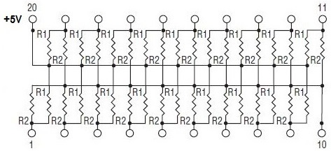
85xx MCA systems use Resistor Networks [RN]
95xx use SCSI Terminators [ST].
Folks, for DECADES the myth-legend was a Red T-Res was NOT capable of Auto-Termination, while the Yellow T-Res IS capable of Auto-Termination. However, after a tortuous consultation with MAJ Tom, a new understanding has been attained...
Doctrine of Signatures [T-Res vs ST]
Not Auto-Terminating - T-Res is socketed.
Auto-Terminating - ST [SCSI Terminator ?] module is soldered to PCB.
T-Res Pinout
This confuses the heck out of me.
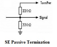
Voltage Divider
The Book of SCSI 2nd Ed ISBN 1-886411-10-7, page 44
Any two resistor values having the ratio of 2/3 and connected to a 5-volt source, would give 3.3 volts at their junction, but these values are chosen because, when placed in parallel (as they appear to be on the SCSI bus), their combined value - (R1 x R2 )/(R1 + R2) -becomes 132 ohms.
Passive terminators have three problems
• Much of the power drawn from TERMPWR (.16 Amps idle, to a max. of .40 Amps per terminator) is wasted in the voltage dividers.
• If the TERMPWR voltage isn't high enough or has noise on it, that problem will be passed on to the SCSI signals being terminated.
• 132-ohm impedance doesn't match that of a typical SCSI cable. In worst-case conditions [pull-up resistor high, pull-down resistor low], the difference could easily add up to 140 mV.
Side View of T-Res DIP
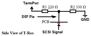
This depiction "flattens" the equivalent circuit and greatly SIMMplifies it.
SCSI Signal Passthrough [Concept]
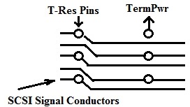
At first, the concept of pulling the T-Res WITHOUT breaking the SCSI signal path was contradicting... But.. what if the T-Res socket pins go into vias in the PCB? How the real SCSI signal conductor traces are laid out on the PCB is a mystery.
Active System Board SCSI Terminators [marked as "ST"]
MAJ Tom:
Aha! I forgot I had a spare Bermuda too.
So yes, it uses the same termination modules as 9585-X. It's a 12-pin SIP package, P/N 42G3371.
The pinout is as follows:
Pin 1: Ground
Pins 2-10: SCSI signal lines (9 signals per pack)
Pin 11: Term. enable
Pin 12: TermPwr (fuse- and diode-protected +5 V, no external regulation)
The term. enable signals of both packs are controlled by pin 52 (Reserved/Ground) of the external SCSI connector. This pin is normally left unconnected and the line is at log. H because of a 10K pull-up resistor to TermPwr. When a cable is connected to the external port, this line is shorted to ground - Log. L. The signal is then inverted/shaped by a 74HC04 invertor, before it goes to the term. enable pins.
The modules on my Bermuda have thinner coating and I can make out 18 discrete components of the same size - 9 per side. These are most likely the 220R and 330R resistors. But there is at least one additional (smaller) component in there - close to the enable pin. Not sure how exactly are they enabling the termination... disconnecting Termpwr/ground from the common side of the resistor doesn't seem right.