INTELLIGENT
PERIPHERAL INTERFACE (IPI)
Disk Interface Design Guide and Users Manual NS App Note 413 Pages 24-25 physical
Simulex IPI Controller External RAID over HPDB50 port. i960CF-25!
Got this card back in the late '90s, no drivers, no info.
SX1601 IPI-2 Disk Drive Interface Protocol Circuit
SX1602A IPI-2 Disk Drive SERDES / Formatter Circuit
Options Increase For Effective Use Of High Performance Winchesters Pg 62-64, 66, 68, 70
The role of the Intelligent Peripheral Interface in systems architecture
INTELLIGENT PERIPHERAL INTERFACE(IPI)
This is the ANSI standard X8T9.3 and is an additional peripheral bus, having higher performance than SCSI. Figure 1.14(a) shows the orientation of the IPI system and the IPI port signals are shown in Figure 1.14(b).
Figure A: IPI Configuration

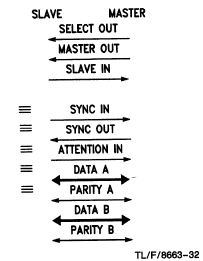
Figure B: IPI Cable Signals
Features
Connects master to a maximum of 8 slaves
Can be used at various levels in the system as shown
Two 8-bit buses (in and out) for commands and status speed protocol and status presentation for fast path
switching
8- or 16-bit parallel transfers
24 signals
Several electrical options; fastest allows 10 Mbytes/sec through a 75 meter cable
Offers both “intelligent” and ‘device level” command definitions, command and data handshaking
50-pin cable ground increases noise immunity
The IPI interface comprises four levels. Level 0 consists of cables, connectors and drivers/receivers. Level 1 consists of state machine and bus protocol. Features of Level 2 are device specific commands, timing critical, physical addressing, physical volumes, command parameters and bus control commands. Features of Level 3 are device generic commands, timing independent, buffered, command stacking, queuing, limited specific commands, logical addressing and physical volumes. Messages are transmitted in packets.
IPI derives its higher performance from a faster handshake and a wider data bus. Two octets, each with a parity line, make up the data interface. Six control lines fill out the interface of 24 signals. There is one master allowed and up to eight slaves on a daisy-chained cable. This master to slave interface is a parallel one and hence IPI 3 could be used, (point 1) in Figure 1.14(a). Each Slave can address up to 16 Facilities, like disk drives. The Slave-to-Facility interface may be IPI 2, (point 2) in Figure 1.13(a), or a lower level interface such as ESDI. Data can be moved at 5 Mbytes/sec in asynchronous mode, 10 Mbytes/sec in synchronous mode. The interface supports various driver options with maximum cable lengths ranging from 5 meters to 125 m.