Interrupt Controller
Interrupt
Controller pages 5-17, HITR - Common Interfaces, 1st
Ed. (Oct 1990)Description
The system provides 16 levels of hardware interrupts. Any interrupt can be masked, including the nonmaskable interrupt (NMI). The interrupt controller must be initialized to the level-sensitive mode; the edge-triggered mode is not supported. Attempts to set the controller to the edge-triggered mode will result in level-sensitive operation. For more information on nonmaskable interrupt, see the
system-specific technical references.
Interrupt Assignments
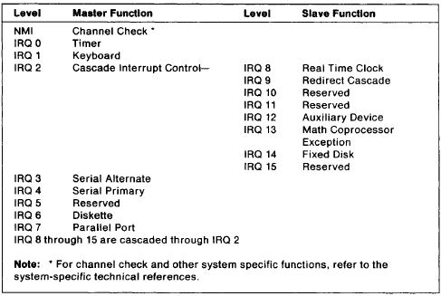
The following figure shows the interrupt assignments, interrupt levels, and their functions. The interrupt levels are listed by order of priority, from highest (NMI) to lowest (IRQ 7). See system-specific technical references for masking interrupts.
Figure 1. Interrupt Level Assignments by Priority
Interrupt Sharing
Hardware interrupt IRQ9Q is defined as the replacement interrupt level for the cascade level IRQ2. Program interrupt sharing should be implemented on IRQ2, interrupt hex 0A. The following processing occurs to maintain compatibility with the IRQ2 used by IBM Personal Computer products:
1. A device drives the interrupt request active on IRQ2 of the channel.
2. This interrupt request is mapped in hardware to IRQ9 input on the slave interrupt controller.
3. When the interrupt occurs, the system microprocessor passes control to the IRQ9 (interrupt hex 71) interrupt handler.
4. The interrupt handler performs an end-of-interrupt (EOI) to the slave interrupt controller and passes control to the IRQ2 (interrupt hex 0A) interrupt handler.
5. The IRQ2 interrupt handler, when handling the interrupt, causes the device to reset the interrupt request prior to performing an EOI to the master interrupt controller that finishes servicing the IRQ2 request.
NOTE: Prior to the programming of the interrupt controllers, interrupts should be disabled with a CLI instruction. This includes the Mask register, EOls, initialization command bytes, and operation command bytes.
Interrupt Controller Registers
The interrupt controller contains the following registers:
* Interrupt Request register
* In-Service register
* Interrupt Mask register
* Initialization Command registers
* Operation Command registers.
Interrupt Request Register and In-Service Register
These registers handle incoming interrupt requests. The Interrupt Request register stores all interrupt levels requesting service. The In-Service register stores all interrupt levels currently being serviced. A priority resolver prioritizes the bits in the Interrupt Request register and strobes the bit with the highest priority into the corresponding bit of the In-Service register.
Both registers can be read by issuing a Read Register command through Operation Command Byte 3, and then reading port hex 0020 or 00A0. The controller keeps track of the last register selected; therefore, subsequent reads of the same register do not require another Operation Command Byte 3 to be written. See “Operation Command Byte 3” on page 12 for more information.
NOTE: After initialization, the controller is set to read the Interrupt Request register.
Interrupt Mask Register
The Interrupt Mask register contains bits that mask each of the interrupt request lines of the Interrupt Request register. Lower priority levels are not affected when a higher priority level is masked.
The contents of this register are placed on the output data bus when -READ is active and port hex 0021 or 00A1 is accessed.
Initialization Command Registers and Operation Command Registers
These registers store commands from the system microprocessor that define initialization parameters and operating modes. See “Programming the Interrupt Controller” on page 8 for more information.
Modes of Operation
The interrupt controller can be programmed to operate in a variety of modes through the Initialization Command bytes and the Operation Command bytes.
Fully-Nested Mode
In the fully-nested mode, interrupts are prioritized from 0 (highest priority) to 7 (lowest priority). This mode is automatically entered after initialization unless another mode has been defined.
NOTE: The priorities can be changed by rotating the priorities through Operation Command Byte 2.
A typical interrupt request occurs in the following manner:
1. One or more ‘interrupt request’ lines are set active, causing the corresponding bits in the Interrupt Request register to be set to 1.
2. The interrupt controller evaluates the requests and sends an interrupt to the system microprocessor, if appropriate.
3. The system microprocessor responds with an ‘interrupt acknowledge’ pulse to the interrupt controller.
4. The controller prioritizes the unmasked bits in the Interrupt Request register and strobes the bit with the highest priority into the corresponding bit of the In-Service register. No data is sent to the system microprocessor.
NOTE: If an interrupt request is not present (for example, the duration of the request was too short), the interrupt controller issues an interrupt 7.
5. The system microprocessor sends a second ‘interrupt acknowledge’ pulse to the interrupt controller.
6. The interrupt controller responds by releasing the interrupt vector on the data bus, where it is read by the system microprocessor.
7. The highest priority in-service bit remains set to 1 until the proper End of Interrupt command is issued by the interrupt subroutine. If the source of the interrupt request is the slave interrupt controller, the End of Interrupt command must be issued twice, once for the master and once for the slave. When the in-service bit is set to 1, all other interrupts with the same or lower priority are inhibited; interrupts with a higher priority cause an interrupt, but the interrupt is acknowledged only if the system-microprocessor interrupt input has been re-enabled by software.
The End of Interrupt command has two forms, specific and nonspecific. The controller responds to a nonspecific End of Interrupt command by resetting the highest in-service bit of those set. In a mode that uses a fully-nested interrupt structure, the highest in-service bit set is the level that was just acknowledged and
serviced. In a mode that can use other than the fully-nested interrupt structure, a specific End of Interrupt command is required to define which in-service bit to reset.
NOTE: An in-service bit masked by an Interrupt Mask register bit cannot be reset by a nonspecific End of Interrupt command when in the special mask mode. See “Special Mask Mode” on page 7 for more information.
Special Fully-Nested Mode
The special fully-nested mode is used when the priority in the slave interrupt controller must be preserved. This mode is similar to the normal nested mode with the following exceptions:
* When the slave’s interrupt request is in service, the slave can still generate additional interrupt requests of a higher priority that are recognized by the master, and initiate interrupts to the system microprocessor.
* Upon completion of the interrupt service routine, software must send a nonspecific End of Interrupt command to the slave and read the slave’s In-Service register to ensure that the interrupt just serviced was the only one generated by the slave. If the register is not empty, additional interrupts are pending, and an End of Interrupt command must not be sent to the master. If the register is empty, a nonspecific End of Interrupt command can be sent to the master.
The special fully-nested mode is selected through Initialization Command Byte 4. See “Initialization Command Byte 4” on page 10 for more information.
Automatic Rotation Mode
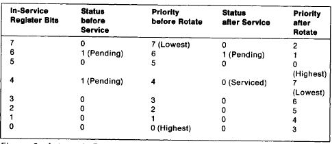
The automatic rotation mode accommodates multiple devices having the same interrupt priority. After a device is serviced, it is assigned the lowest priority and must wait until all other devices requesting an interrupt are serviced once before the first device is serviced again.
The following example shows the status and priorities of the In-Service register bits before and after bit 4 of the Interrupt-Request register is serviced by a Rotation on Nonspecific End of Interrupt command.
Figure 2. Automatic Rotation Mode
The automatic rotation mode is selected by issuing a Rotation on Nonspecific End of Interrupt command through Operation Command Byte 2. See “Operation Command Byte 2” on page 11 for more information.
Specific Rotation Mode
The specific rotation mode allows the application programs to change the priority levels by assigning the lowest priority to a specific interrupt level. Once the lowest-level priority is selected, all other priority levels change. The following example compares the normal-nested mode to the specific rotation mode with bit 5 of the
interrupt Request register set to the lowest priority.
Figure 3. Specific Rotation Mode when IRQ5 Has the Lowest Priority
Interrupt Request Register Bits;Nested Mode Priority Level;Specific Rotation Mode Priority Level
7;7 (Lowest);1
6;6;0 (Highest)
5;5;7 (Lowest)
4;4;6
3;3;5
2;2;4
1;1;3
0;0 (Highest);2
The specific rotation mode is selected by issuing a Rotate on Specific End of Interrupt command or a Set Priority command through Operation Command Byte 2. See “Operation Command Byte 2” on page 11 for more information.
Special Mask Mode
The special mask mode allows application programs to selectively enable and disable any interrupt or combination of interrupts at any time during its execution. The special mask mode is selected through Operation Command Byte 3. Once the controller is in the special mask mode, setting a bit in Operation Command Byte 1 sets a corresponding bit in the Interrupt Mask register. Each bit set in the Interrupt Mask register masks the corresponding interrupt channel. Interrupt channels above and below a masked channel are not affected. See “Operation Command Byte 1” on page 11 and “Operation Command Byte 3” on page 12 for more information.
Poll Mode
Before the poll mode can be used, a CLI instruction must be issued to disable the system-microprocessor interrupt input. Devices are serviced by software issuing a Poll command through Operation Command Byte 3. The first ‘read’ pulse following a Poll command is interpreted by the controller as an ‘interrupt acknowledge’ pulse; the controller sets the appropriate in-service bit and reads the priority level. The byte placed on the data bus during a ‘read’ pulse is shown in the following figure.
Figure 4. Poll Mode Status Byte
Bit;Function
7;Interrupt Present
6-3;Undefined
2-0;Highest Priority Level
Bit 7 This bit is set to 1 if an interrupt is present.
Bits 6-3 These bits are not used and may be set to either 0 or 1.
Bits 2-0 These bits contain the binary code of the highest priority level requesting service.
Level-Sensitive Mode
The interrupt controller cannot be placed in the edge-triggered mode. In the level-sensitive mode, interrupt requests are recognized by a high level on the interrupt-request input. Interrupt requests must be removed before the End of Interrupt command is issued to prevent a second interrupt from occurring.
Programming the Interrupt Controller
Before the system can be used, the interrupt controller must be programmed with four sequential initialization commands. When a command is issued to a master at port hex 0020 (or a slave at port hex 00A0) with bit 4 set to 1, the command is recognized as Initialization Command Byte 1. Initialization Command Byte 1 is the
first of four initialization commands required to program the interrupt controller. The following events occur during the initialization sequence:
1. The level sense circuit is set to the level-sensitive mode. (Following the initialization procedure, interrupts are generated by a high level on the interrupt-request input.)
2. The Interrupt Mask register is cleared.
3. IRQ7 is assigned priority 7.
4. The slave mode address is set to 7.
5. The special mask mode is cleared and the controller is set to read the Interrupt Request register.
Once the interrupt controller is programmed by the initialization command bytes, the controller can be programmed by the operation command bytes to operate in other modes.
NOTE: The master interrupt controller must be initialized before the slave interrupt controller. Failure to do so will cause unexpected results.
Initialization Command Byte 1
This is the first byte of the 4-byte initialization command sequence. This byte is issued to either the master (port hex 0020) or the slave (port hex 00A0).
Figure 5. Initialization Command Byte 1
Bit;Function
7-5;Reserved — Must be set to 0.
4;Initialization Command Byte 1 Identifier — Must be set to 1.
3;Level-Sensitive Mode — Must be set to 1.
2;Call Address Interval of 8 — Must be set to 0.
1;Cascade Mode — Must be set to 0.
0;4-byte Initialization Command Sequence — Must be set to 1.
Initialization Command Byte 2
This byte defines the address of the interrupt vector. Bits 7 through 3 define the five high-order bits of the interrupt vector address. Bits 2 through 0 are initialized to 0 and replaced by the hardware interrupt level when an interrupt occurs. This byte is issued to either the master (port hex 0021) or the slave (port hex 00A1).
Figure 6. Initialization Command Byte 2
Bit;Function
7-3;Bits 7 - 3 of the interrupt Vector Address
2-0;Initialized to 0
Initialization Command Byte 3
This byte loads a value into an 8-bit slave register.
* In the master device mode, this byte has a value of hex 04 to identify interrupt 02 as a slave providing the input request.
* In the slave device mode, this byte has a value of hex 02 to tell the slave that it is using hardware interrupt 02 to communicate with the master. The slave compares this value to the cascade input; if they are equal, the slave releases the interrupt vector address on the data bus.
This byte is issued to either the master (port hex 0021) or the slave (port hex 00A1).
Figure 7. Initialization Command Byte 3
Bit;Master Function;Slave Function
7-3;0;0
2;1;0
1;0;1
0;0;0
Initialization Command Byte 4
This byte is issued to either the master (port hex 0021) or the slave (port hex 00A1).
Figure 8. Initialization Command Byte 4
Bit;Function
7-5;Reserved — Must be set to 0.
4;Special Fully-Nested Mode
3,2;Reserved — Must be set to 0.
1;Normal End of Interrupt — Must be set to 0.
0;80286/80386 Microprocessor Mode — Must be set to 1.
Operation Command Byte 1
This byte controls the individual bits in the Interrupt Mask register.
This byte is issued to either the master (port hex 0021) or the slave (port hex 00A1).
Figure 9. Operation Command Byte 1
Bit;Function
7-0;Interrupt Mask Bits 7 - 0
Bits 7-0 When set to 1, these bits inhibit their respective interrupt request input signals.
Operation Command Byte 2
This byte controls the interrupt priority and End of Interrupt command.
This byte is issued to either a master (port hex 0020) or a slave (port hex 00A0).
Figure 10. Operation Command Byte 2
Bit;Function
7;Rotate Mode
6;Set interrupt Level
5;End of Interrupt Mode
4-3; Reserved — Must be set to 0
2-0;Interrupt Level (When bit 6 = 1)
Bits 7-5 These bits define the rotate mode, end of interrupt mode, or a combination of the two, as shown in Figure 11 on page 12.
Figure 11. Operation Command Byte 2 (Bits 7 - 5)
Bit 7;Bit 6;Bit 5;Function
0;0;0;Reserved
0;0;1;Nonspecific End of Interrupt Command
0;1;0;No Operation
0;1;1;Specific End of interrupt Command *
1;0;0;Reserved
1;0;1;Rotate on Nonspecific End of Interrupt Command
1;1;0;Set Priority Command**
1;1;1;Rotate on Specific End of Interrupt Command **
NOTE: * Bits 0, 1, and 2 are the binary level of the in-service bit to be reset.
** Bits 0, 1, and 2 are the binary level of the lowest-priority device.
Bits 4,3 These bits are reserved and must be set to 0.
Bits 2-0 These bits define the hardware interrupt level to be acted upon when bit 6 is set to 1.
Figure 12. Operation Command Byte 2 (Bits 2 - 0)
Bit 2;Bit 1;Bit 0;Function
0;0;0;Interrupt Level 0
0;0;1;Interrupt Level 1
0;1;0;Interrupt Level 2
0;1;1;Interrupt Level 3
1;0;0;Interrupt Level 4
1;0;1;Interrupt Level 5
1;1;0;Interrupt Level 6
1;1;1;Interrupt Level 7
Operation Command Byte 3
This byte is issued to either a master (port hex 0020) or a slave (port hex 00A0).
Figure 13. Operation Command Byte 3
Bit;Function
7;Reserved — Must be set to 0.
6,5;Special Mask Mode Bits
4;Reserved — Must be set to 0.
3;Reserved — Must be set to 1.
2;Poll Command
1,0;Read Register Command
Bit 7 This bit is reserved and must be set to 0.
Bits 6,5 These bits enable the special mask mode, as shown in the following figure.
Figure 14. Operation Command Byte 3 (Bits 6 and 5)
Bit 6;Bit 5;Function
0;0;No Action
0;1;No Action
1;0;Normal Mask Mode
1;1;Special Mask Mode
Bit 4 This bit is reserved and must be set to 0.
Bit 3 This bit is reserved and must be set to 1.
Bit 2 When set to 1, this bit sets the Poll command.
Bits 1,0 These bits determine the register to be read on the next ‘read’ pulse, as shown in the following figure.
Figure 15. Operation Command Byte 3 (Bits 1 and 0)
Bit 1;Bit 0;Function
0;0;No Action
0;1;No Action
1;0;Read Interrupt Request Register
1;1;Read In-Service Register