INMOS IMS B017 IBM PS/2
Motherboard
@6A03.ADF "INMOS IMS B017 TRAM Motherboard"
INMOS IMS B017 IBM PS/2 Motherboard
IMS B017 User Guide and Reference Manual, Inmos Limited, 1990 [ ? ]
IMSC012-P20S Datasheet
IMS S217 IMS B017 Driver for PS/2 [missing !]
Software distributed on 720 Kbyte 3.5 inch IBM format floppy disks.
DOS 3.0 at a minimum
Note: It -MIGHT- contain Innn.ADF files for initialization. LFO
Note: S217 uses 720KB 3.5" floppies. Other boards may use 5.25" or QIC tape.

IMS S217 a.k.a. PS/2 Motherboard Support Software
Features
IBM PS/2 compatible OS/2 device driver
INMOS server program, including sources
Transputer network mapping tool
Included with IMS B017
Product code: IMS S217
Allows transputer network access to:
PS/2 filing system
Screen and keyboard
OS/2 system functions
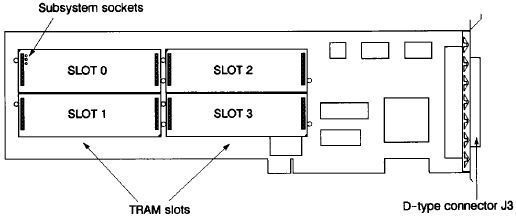
TRAM Slots
The IMS 8017 has four TRAM slots. Each slot can accommodate a size 1 TRAM. Size 2 TRAMs can be fitted, occupying two slots. Each of the four slots on the IMS B017 has connections for four INMOS links. Links are numbered 0 to 3 and slots, in the case of the IMS B017, are numbered 0 to 3.
The four slots on the IMS 8017 are connected into a pipeline, using links 1 and 2 from each slot. So slot 0, link 2 is connected to slot 1, link 1; slot 1, link 2 is connected to slot 2, link 1 and so on.
In some cases not all of the slots of the IMS B017 will have TRAMs fitted. Even if they are covered by a TRAM they may not be connected to it electrically. In this case to maintain the pipeline connection pipejumpers must be used, plugged into each un-occupied slot, or the TRAM covering that slot. These pipejumpers connect link 1 to link 2 of the same slot. They are plugged into the pin 1 end of the TRAM slot, with the triangle marked on the corner. The pipejumpers have a mark on them which must be pointing towards the pin 1 marker triangle.
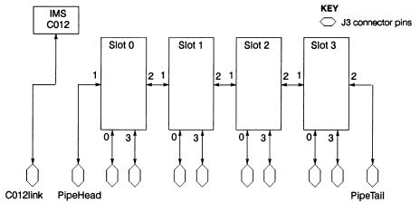
The two unconnected links, slot 0, link 1 and slot 3, link 2, at the ends of the slot pipeline are referred to as pipehead (slot 0, link 1) and pipetail (slot 3, link 2). Pipetail, pipehead, links 0 and 3 from each slot, and the link from the IMS C012 are taken out to the 37 way D-type connector, J3, at the back of the board.
By connecting links together on J3, networks of transputers can be set up on the IMS B0I7. These networks can also extend onto multiple IMS B0I7s, or onto other transputer boards, by connecting the links on J3 to the links coming out to an extemal connector on the other boards. The INMOS link connections between the slots, J3, and the C012 Link from the IMS C012 are shown In figure 38.2.
MCA Bus Interface Block Diagram
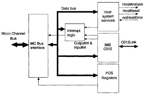
The bus interface on the IMS B017 performs four functions :
1 Provide POS registers used by PS/2 setup utilities in configuring IMS B017.
2 Convert 8 bit parallel MC bus transfers <--> serial INMOS link transfers
3 Providing a system services port.
4 Generating interrupts on events on link interface or transputer error asserted
A block diagram of the Micro Channel bus interface is given in figure 38.3. To enable control of the bus interface functions from software running on the Micro Channel based system, the MC bus interface has a number of registers mapped Into the I/O address space of the Micro Channel bus (separate from the memory address space). Details of these are given in [1].
Link interface
An IMS C012 link adaptor is used as the basis of the link interface on the IMS 8017. Detailed information on this device can be found in [2]. This device performs the parallel data to serial lNMOS link conversions in both directions in a similar fashion to a UART device used on an RS232 interface. The link coming from the link adaptor Is labelled C012Link in figure 38.3. The IMS C012 has four registers which can be written to or read by the Micro Channel bus, more information Is given in [1].
Host system services
A port is provided by the Micro Channel bus interface to allow software on the MC based system to provide 'system services' to transputers connected to the IMS B017, either as TRAMs plugged into the board or transputers on other boards. The port appears as two registers in the I/O map of the Micro Channel. In addition
an extra register, the Error Status/Interrupt Control register allows the state of the notError signals from each of the TRAM slots to be monitored. The system services port and the error status register function is described in [1].
Interrupts
The IMS B017 can generate an interrupt on the Micro Channel bus when one of the following events occurs:
• notHostError is asserted
• The Outputlnt signal from the IMS C012 is asserted
• The Inputlnt signal from the IMS C012 is asserted
Generation of interrupts on each of these events is controlled by two interrupt enable bits in the Output Status register and Input Status register, and bit 0 of the Error Status/Interrupt Control register. Setting a bit to one in one of these registers enables interrupts on the event corresponding to that bit.
Configuration
Configuration of the IMS B017 is carried out by installing any TRAMs required on the board, selecting options by using the system configuration utilities supplied by IBM with the PS/2, and by making connections to the 37 way D-type, J3, on the back of the board. Further information on setting the IMS B017 configuration is given in [1].
IM8 B017 memory map
| Addresses: | Register |
| Board base address + #00: | Link adaptor input data register |
| Board base address + #01: | Link adaptor output data register |
| Board base address + #02: | Link adaptor input status register |
| Board base address + #03: | Link adaptor output status register |
| Board base address + #10: | Reset/Error register |
| Board base address + #11: | Analyze register |
| Board base address + #12: | Error status/Interrupt control register |
Board base address can be set to #0150 or #0200
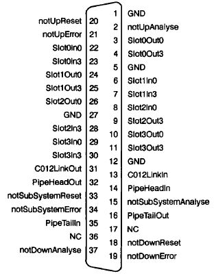
J3 Pinout [DB37]
@6A03h.ADF Sections for "INMOS IMS B017 TRAM Motherboard"
NumBytes 1
I/O Base Address
Select either 0150h-016Fh or 0200h-021Fh.
<"150">, 200
Link Speed Selection
<"All 10 Mbit/s">, A=0 B=1, A=1 B=0, All 20 Mbits/s
NOTE: "0" = 10Mb/s, "1" = 20Mb/s LFO
Slot 0 System Services
TRAM Slot 0 can be Up system services or Host system services from the PS/2.
<"Host Serv">, Up Serv
Slots 1-3 System Services
TRAM Slots 1 to 3 can be either Subsystem services or Down system services
<"Subsys Serv">, Down Serv
Interrupt Select
Select 3, 5, 6, or 7 NOTE: No mention if shareable LFO]
<"IRQ3">, 5, 6, 7