Taming the Nineteen-Seventeen Bolt
By “SNIPER”
American Rifleman, vol 63, No. 24, Mar 9, 1918 – pages 467, 469, 472
IN the hands of an inexperienced or amateur artificer, the bolt of the United States Rifle, Model 1917, is potentially a dangerous bit of mechanism. To carelessly undertake to dismount the bolt is tantamount to inviting sundry minor injuries, with the possibility of serious hurt, for the mainspring has considerable force in its stout coils which it will expend upon the unwary on the slightest provocation. Also the problem of fitting new strikers to the rifle has brought much puzzlement to the uninitiated, since each is issued with a knob on the striking end, the purpose of which has not been apparent to many who have undertaken this very frequently necessary repair job.
But first let's consider the matter of dismounting the bolt, since that must be accomplished before the new striker is seated, and since that is the operation which holds an element of danger. Those who have studied the working of the new weapon with which the National Army is to be equipped can not have failed to note that in order to reduce the bolt of this rifle to its component parts a much more involved and difficult process must be followed than in performing the same operation with the Springfield;
These difficulties go hand in hand with a certain amount of danger, for, if the heavy mainspring, fully compressed, slips from the operator’s grasp, the striker may be sent flying in any direction, propelled by a force sufficient to cause serious injury. Wherefore, in publishing the official description and rules for management of the I917, the ordnance officials responsible for this little volume thought it necessary to add to the directions for dismounting the bolt, by means of a loop of string over the cocking piece hook, this warning:
“Relieve the spring from stress slowly, * * * being careful that the parts do not fly from the hand.”
With the Springfield bolt, no such care is imperative, for as all riflemen who have tinkered with the Model 1903 well know, the tension of the spring is partially relieved by allowing the cocking piece to move forward in the sleeve during the operation.
But the need which prompted the warning in the official description of the Model 1917 has been amply demonstrated by sundry mishaps throughout the cantonments where the Model 1917 Rifle has made its appearance.
Take any group of a score of men, and among its members can be found one or more who will exhibit a set of skinned knuckles or a split finger acquired at some point in the process of dismounting or assembling the bolt of the 1917 as laid down in the official rules and regulations governing the use of the arm. And here and there—although in much more isolated instances—one who inquires concerning the behavior of the new bolt when it is being taken apart may hear how a striker flew from a bolt, penetrating a file of papers an inch in thickness; how another buried its sharp point in the side of an army locker; how a third skittered skyward, to be stopped only when it imbedded itself in the barrack ceiling. Wherefore it would appear that all precautions which can be taken to prevent such occurrences are amply justified.
Now, men in the service do not habitually dismount and assemble the bolts of their rifles by way of amusement. Occasions arise both in the proper care of the piece, and in making repairs, when it is necessary to remove the striker. It must not be assumed, however, that the idiosyncrasies of the 1917 bolt in any way detract from the weapon as an excellent service arm, and the thing for every man to do is to learn how to safely muzzle the heavy mainspring so that it cannot bite.
When Great Britain adopted the Model 1914 which formed the basis upon which the U. S. Model 1917 was constructed, her soldiers encountered the same trouble when it came to removing the mainspring. Therefore the British experts devised a tool by which the sleeve, cocking piece and striker could be removed from the bolt without trouble.
This device consisted of a piece of tubular steel, notched in such a way that when it was slipped over the end of the cocking piece it operated to permit the sleeve, cocking piece and striker to be unscrewed from the bolt. This much, however, the American rifleman has accomplished merely by the use of a penny in which a notch has been cut. Where the British tool and the American penny device stop, however, is far short of the danger line. After the sleeve, cocking piece and striker are removed from the bolt, it is still necessary to cope with the heavy mainspring, and that is where the danger lies.
American ingenuity, however, has met and conquered the 1917 bolt, which incidentally has a much stronger spring than its English prototype, so that while now knuckles are being bruised and fingers split taking out strikers, it will be possible in a short time for every man to perform this operation whenever necessary with ease and perfect safety.
This is accomplished by the use of a simple tool. It consists of a piece of steel 1 inch wide, 1/16 of an inch thick, and 5 9/16 inches long. At one end the steel is bent at right angles, ½ an inch from the end of the bar. In the middle of this angle a notch ¼ of an inch wide and 3/8 of an inch deep is cut. At the other extremity, the steel is bent at a right angle 1 9/16 inches from the end. In this a circle ¾ of an inch in diameter is bored, with a notch 5/16 of an inch square cut from the circumference at the top.
The circle and the two notches provide all that is necessary for quickly and, what is more, safely dismounting the 1917 bolt and assembling it. The tool was devised by Major C. B. Winder, of the Ordnance Department, after he had been impressed with the need for such a device. A patent upon it is pending.
With this tool in a few seconds the Major can have the bolt entirely apart, and almost as quickly assemble it. The tool accomplishes all that the British tool or the device made from a copper penny can do, and in addition makes it possible to accomplish the dismounting of the sleeve, cocking piece and striker simultaneously with the operation of taking these pieces from the bolt.
In order to understand the use of the tool, it is necessary to speak of the ¾ -inch circle as the “assembling ring”; the notch which runs from the ring, the “dismounting slot,” and the notch in the other end of the tool, as the “assembling notch.” Bearing these designations in mind, the use of the tool is as follows:
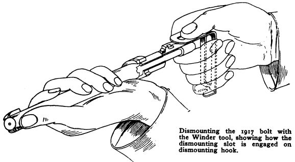
To Dismount the Bolt
Remove the bolt from the rifle, and grasp it in the left hand. Grasp the tool in the right hand, so that the assembling ring of the tool rests on the forefinger, between first and second joints, ball of thumb resting on the assembling ring, so that the dismounting slot is in front of end of thumb. Hook the dismounting slot of the tool on dismounting hook on the cocking-piece lug, and draw the cocking piece out until the lug clears the end of the sleeve. Then, turn a quarter turn to right and cocking piece will slip from striker and remain in the tool between thumb and fore-finger, and at the same time the force of the mainspring is expended inside the bolt. Unscrew sleeve from bolt. Remove mainspring from
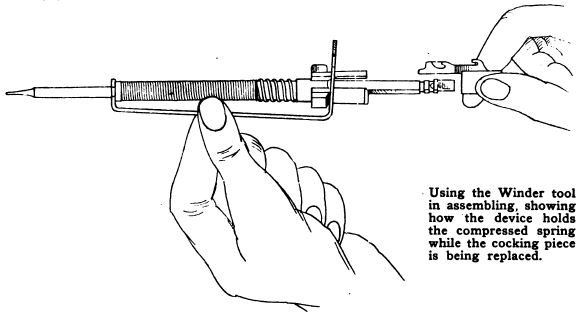
To Assemble the Bolt
Slide the mainspring over striker. Hold the point of the striker against a wood or similar surface, and, placing the sleeve against the end of the spring, with the flats in its bore registering with the flats on the striker, compress the spring slightly and slip the assembling ring of tool over sleeve, then grasp the tool with both hands, and compress the spring by forcing the sleeve toward the point of the striker and engage the tool on striker with the assembling notch just below collar. This holds the spring fully compressed. Replace the cocking piece on the end of the striker and lock it by turning it so that its lug will rest on rear end of sleeve, very close to the left side of the lug slot in the sleeve, when the tool is removed and spring released. Screw sleeve into bolt by grasping large part of sleeve between thumb and forefinger. Caution: If lug of cocking piece is grasped, it is liable to slip and cause injury. Hook tool on dismounting hook and replace lug in lug slot in sleeve. Place lug in half-cock notch. Replace bolt in rifle.
Time required, about 1 minute. There is another matter in connection with the bolt of the 1917 rifle which is apparently causing some misunderstanding in the cantonments. This is in connection with the replacing of broken strikers.
All strikers which are included in supplies of “spare parts” are sent out with small knobs on the firing end. This circumstance has caused a great deal of misunderstanding among men used to handling only the standardized Springfield firing pins, which are sent from the armories ready to slip into any rifle which may be in need of such a part. For the benefit of those who have attempted to replace broken strikers with extra strikers taken from the spare parts chest, and who have wondered why the knobs are in evidence, some little explanation may not be out of order.
The knob on the extra strikers is the ”Stop, Look and Listen” warning of the Ordnance Department. Translated, it means, “This striker must be carefully fitted to the individual rifle in which it is to be used before it can be considered absolutely safe.” It all came about in this wise:
When under stress of actual war the Ordnance Department undertook to turn out millions of rifles, to have manufactured every rifle with the particularity which is necessary to insure absolute interchangeability would have been impossible. Under the conditions, a certain amount of latitude had to be allowed on every bearing point in the bolt, since to machine the points uniformly to within one-thousandth of an inch could not be accomplished. This policy necessitated a “point of compensation” where, so to speak, the “slack” could be caught up. For this particular point of compensation the point of the striker was selected.
Now, in the manufacture of the Model 1917, a latitude of .006 of an inch is permitted in the fit of the face of the bolt, in relation to the rear face of the standard steel-test cartridge which is used as a gauge in all rifles before they are issued. With this distance varying from a fit which is accurate to within .001 of an inch to .006 of an inch, it can be seen that no set of strikers, made precisely the same length, can be interchanged between rifles. If the strikers were made to work in a rifle where the distance between the face of the bolt and the rear face of the test cartridge was .003 of an inch, this size of striker put in a rifle which chanced to be absolutely accurately tooled would be so long as to drive through the primer, puncturing it and causing the dangerous “spit” with which riflemen have become familiar. On the other hand, if this striker were used in a rifle where the distance in question was the full .006 of an inch permitted, the striker would be too short and the bolt impotent.
When rifles are assembled at the armory, each striker is fitted to the individual rifle in which it is to be used. This practice must be followed in the field; that is the why and the wherefore of the knob on the end of the spare strikers. At present the Ordnance Department is furnishing with all spare parts a tool for filing down and fitting the spare strikers. The knob is not a mistake nor an oversight. It was put on the strikers on purpose, to call attention to the fact that each must be separately tooled for the rifle in which it will be inserted.