OPTICAL INSTRUMENTS have been developed for
sighting ordnance material in order to increase the accuracy with
which a piece can be laid upon a given target. In order to derive
the full benefit of this valuable invention, it is a prime requisite
that the instruments be correctly adjusted. This adjustment may be
divided into two parts.
First, the instrument must be so assembled that the lenses and
sighting mark within the instrument are properly spaced and aligned.
Secondly, the instrument must be attached and
aligned to the gun so that the shot strikes upon the target when the
sighting mark in the telescope is superposed upon the image of the
target. I shall here deal with the adjustment of the first kind, as
the second adjustment is already familiar to all users of telescopic
sights.
In order that a fixed telescope shall always point
directly at a fixed target no matter what the position of the eye,
it is essential that the image of the target, as formed by the
objective and erecting system, is exactly in the plane of the cross
wires or other sighting mark. The eyepiece must be so adjusted that
its focal plane exactly coincides with the plane of the cross wires.
This being done the eye may be moved clear across the field without
there being any displacement of the image from the cross wires. If
an instrument is not so adjusted, when the eye is moved away from
the center of the lens, the cross wires and image separate, i.e.,
the cross wires appear to jump over to one side, producing what is
called parallax, a defect which makes it impossible to duplicate
shots, as a very slight displacement of the eye from the center of
the lens causes the image and cross wires to assume different
relative positions, with resulting displacement of the shots on the
target.
In adjusting any telescope with cross wires, the
first operation is always to point the telescope to the clear sky or
any uniformly illuminated surface, and move the eyepiece in or out
until the position is found where the cross wires appear blackest
and most sharply defined. In some telescopes the eyepiece is fixed
and focusing is accomplished by moving the cross wires. In this case
move the cross wires until position of maximum sharpness is
obtained. The telescope should then be put in a steady rest and
sighted upon the target, at the distance at which it is to be used,
and it is important that the telescope be held firmly fixed.
The scope is now focused upon the target by moving
the objective lens in or out until the target is sharply defined.
Due to the large range of accommodation of the human eye it is not
possible to tell exactly when the position of best focus is reached
by judging the image alone. The final setting of the objective is
accomplished by the parallax method. The head is quickly nodded
slightly up or down, or from right to left, and the image observed
carefully to see if the cross wires appear to jump. The objective is
now moved very minute distances in or out, until a position is found
at which the cross wires jump the least. Now move the eyepiece in or
out a very little at a time, until a position is found where the
jumping or parallax entirely disappears. The optical system is now
in correct adjustment, and the position of the eyepiece and
objective should be securely clamped.
When the sight is to be used on several widely
differing ranges the adjustment may be made for the shortest range
and the objective focused for the longer ranges and the position of
the objective locking device marked carefully upon the tube with a
very fine line and the range marked opposite.
After the scope is once adjusted for any range the
eyepiece should never be disturbed, all focusing for different
ranges to be done by moving the objective only.
In some cases the shooter will meet with a. condition in which he
will find one wire will show parallax, while the other will not move
at all. This condition is caused by astigmatism, which may be either
in the observer's eye, or in the lenses of the scope.
In order to determine whether the astigmatism is in
the telescope or the eye, observe carefully which wire has parallax,
and rotate the telescope 90 degrees, and test for parallax. If the
scope has astigmatism, the wire which appeared to jump the first
time will remain quiet, while the other wire will show parallax. If
the same wire appears to jump in both cases the trouble is in the
shooter’s eye. Astigmatism in the eye can not be overcome by any
amount of focusing.
It can only be corrected by the shooter having glasses fitted to his
eyes to correct his vision to normal. A shooter who has astigmatic
eyes must either wear his glasses when shooting, or have one of his
spectacle lenses trimmed down and properly mounted in the eyepiece
of his scope. A shooter who is near or far sighted only, can shoot
with out his glasses, as he can focus the eyepiece for his eyes when
adjusting the scope.
If the scope itself shows astigmatism, the only remedy is to have
the lenses corrected.
This phenomena of one wire remaining apparently quiet and the other
apparently jumping is known as cross parallax. It is caused either
by the surface of some lens being cylindrical instead of spherical,
or by strain in the glass. This latter may be caused by improper
annealing, or some lens being mounted too tightly in its cell.
Lenses should not be too closely mounted, as contraction of the
mount in extreme cold will often strain the lenses sufficiently to
cause cross parallax and affect the sharpness of the image.
This method of adjusting a sight seems very long and
difficult when written thus at length, but in practice it is short
and precise. An experienced observer can adjust a sight in a
surprisingly short time, and during the war experienced adjusters
frequently adjusted fifteen or more scopes per hour.
NOTE: I have tried
to get the subscripts correct, but even though I think
they are correct, I’m no optical scientist. If any reader can
provide correction to the varied identifiers or other parts of
this period article, please send me a note HERE
so I can correct things.
NOTE—This is the first of a number of
articles dealing with glass sights which Mr. Fecker, an optical
engineer, has prepared. The second will appear in an early
issue.
THE theory of the telescopic sight is
practically the same as the theory of the terrestrial telescope.
The only difference is that a set of cross wires is inserted in
the optical system and the focal lengths of the lenses are so
chosen that a long eye relief is obtained.
The telescopic sight consists primarily of an
object glass, which forms a small inverted image of the object, an
erecting system which turns the image right side up, and an
eyepiece which magnifies the image formed by the objective.
Terrestrial telescopes are classified according
to the means used for erecting the image, into prismatic and
non-prismatic. The two different kinds each have their advantages
and disadvantages. As the non-prismatic sight is the one most
frequently used, this type will be described first.
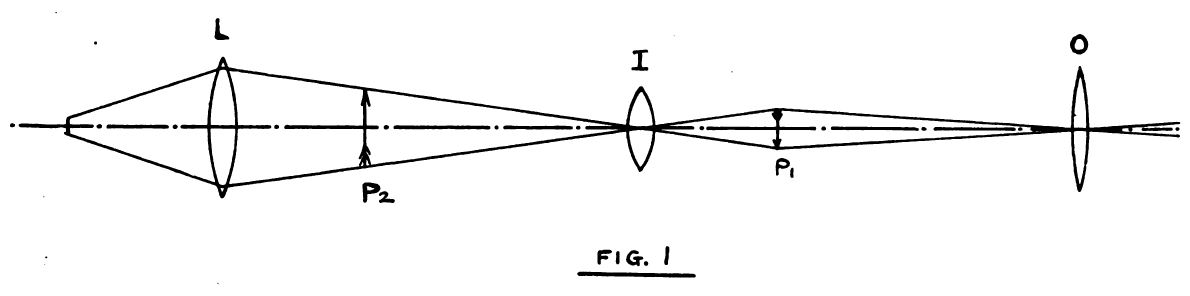
The non-prismatic sight consists of an
objective O, an inverting system I and an eyelens E. The objective
forms an image at P, which is inverted both up and down and right
and left, or, in other words, the objective gives complete
inversion. The size of this image is equal to the angular size of
the target as seen from the position of O, multiplied by the focal
length OP1, of the objective. As the point P1
is at the focal plane of the objective, the cross wire may be
placed at this point. The point P1, is the conjugate
focal point of the erecting lens I, whose other conjugate point is
the second image point P2. The points P1 and
P2 are related to the lens I as given by the simple
formula 1/IP1 + 1/IP2 = 1/F1 where
F2 is the focal length of the erecting lens I. When IP1is
equal to IP2 the image P, is exactly the same size as P2,
but if IP1 is smaller than IP2, the image P2
is larger than P1, and the inverting lens helps magnify
the image P1.
In order that the image P2 may be
distinctly seen by the eyelens E, the point P2 must be
in the focal plane of the eyelens. The cross wire may also be
located at P2. The total magnification of the scope is
the ratio of the focal length of the objective to the focal length
of the eyepiece, multiplied by the ratio of IP2 to IP1.
At the point P1 or P2, a
diaphragm is placed, which limits the field of view and also
serves to support the cross wires.
The lens O is generally quite small, usually ½
to 9/16 inch diameter. The lens I must be of such size that it
takes in the complete cone of rays of the objective, and the
eyelens is chosen of such size that it allows the full field, as
determined by the diaphragm, to be used when the eye is located at
the proper position. The distance from the eyelens to the eye
position is known as the longitudinal eye relief. The position of
the eyepoint can be readily computed from the formula for
conjugate foci as given for the erecting lens, when one remembers
that the erecting lens I forms an image of the objective at some
point between I and P2. This image of the objective,
then becomes the one conjugate point for the eyelens, the other
point being the position of the eye. At this second point is a
small circle of light called the exit pupil, which is really an
image of the objective as formed by the erecting lens and the
eyelens. The diameter of this circle of light can be measured, and
knowing the clear diameter of the objective, the magnification can
be obtained directly by dividing the clear diameter of the
objective by the diameter of the exit pupil.
The diagram, Fig. 1, represents the simplest
form of telescope, but in practice the lenses are never single
lenses, but systems of lenses. The simplest scope consists of a
single lens for an objective, a pair of lenses for an erecting
system, and a single lens for an eyepiece. None of these lenses
are achromatic, and as a result this form of scope can be used
only for low powers. When two single lenses are used for an
inverting system, a diaphragm must be inserted between them,
otherwise bad blurring of the image results. This type or sight is
also made with two lenses for an eyelens. This type of sight with
the non-achromatic lenses represents the cheapest form of sight
which is built.
As a single lens always has more or less color
error, due to the fact that a single lens cannot focus all the
colored rays of light at the same point, achromatic lenses have
been introduced to get a better image. These lenses consist of two
lenses, one of crown glass and one of flint glass, whose radii of
curvature and the glass of which they are made, is so chosen, that
the residual errors of achromatism are too small for the eye to
perceive. With an achromatic lens, the curves can also be so
chosen as to eliminate curvature of field and distortion of image
which are ever present in a single lens.
In the achromatic sight the objective consists
of two lenses cemented together. The inverting lens may consist of
one or two achromatic lenses. Where the construction calls for a
short focus inverting lens of relatively large aperture, it is
necessary to use two achromatic lenses which are exactly alike and
turned back to back. A single short focus lens of large diameter
cannot be used as an inverting lens due to its serious errors of
coma, distortion and astigmatism, so in order to obtain the short
focal length, two lenses, each of double the desired focal length
are used, and placed as nearly in contact as possible. The focal
length of such a combination is practically one-half the focal
length of either lens.
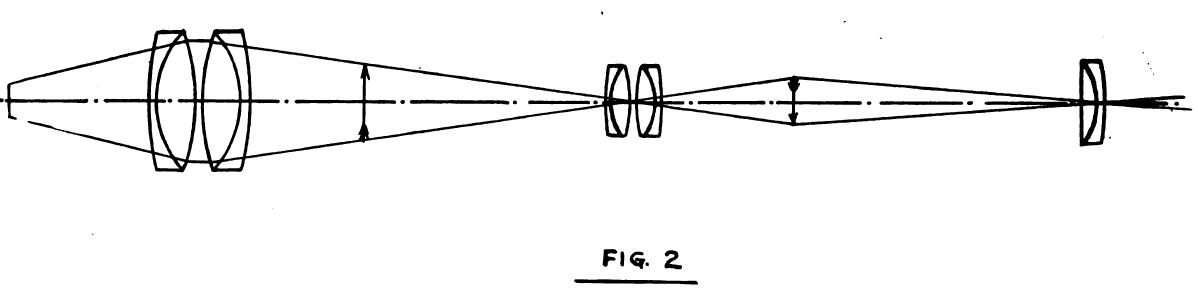
In the same manner the eyelens may consist of
one or two achromatic lenses. The size of the eye lens is
determined by the size of the field, and with a long eye relief
and large field the eyelenses become very large. To make a short
sight with a very large field and long eye relief is indeed a
severe test of the optician’s skill, for with increasing size of
field, and the short focus lenses required to get a short sight,
the residual errors of the optical system become very pronounced,
and it is a problem to get a large field, flat through out, with
image well defined over its entire area, free from distortion,
color errors, or astigmatic errors, and to have it uniformly
illuminated.
Such a sight is shown in Fig. 2. Generally
speaking, the longer the focus of the different lenses, the easier
it is to get long eye relief and also better definition, while the
shorter the sight the more the optical difficulties increase.
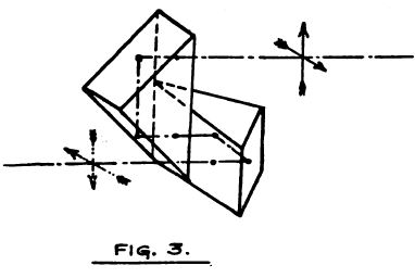
Of the prismatic sights, there are but three
general types in use. The simplest from an optical standpoint is
the sight which uses Porro prisms to erect the image.
These are merely right-angled prisms with their
hypotenuses placed together, and their main axes at right angles
to each other. The objective completely inverts and forms an
inverted image, the first prism inverts right and left, the second
prism inverts up and down, so that the image which reaches the
eyepiece is again erect and right side to. The other two prismatic
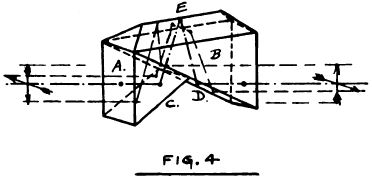
sights employ a roof prism for erecting the image.
The first of these is shown in Fig. 4 and
consists of two prisms. Prism A is a simple 60-degree prism. Prism
B has a ridge or roof at its upper side. The reflections at C and
D invert up and down. The double reflection in the roof faces E,
invert right and left, so that the completely inverted image from
the object is presented to the eyepiece as a completely erected
image by the prism system.
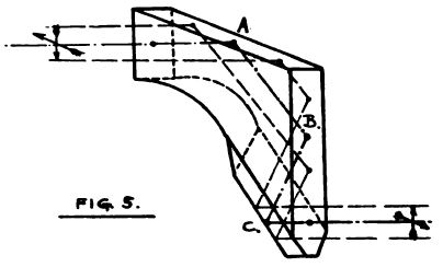
The third type of prism sight has a prism made
in one piece, of the type shown in Fig. 5. The reflections at A
and B invert up and down while the double reflection in the roof
at C inverts right and left. Both of the last two types of prism
are very expensive to make. The roof angle must be corrected by
hand retouching which is a slow operation requiring the greatest
skill. The angle of the roof must be exactly 90 degrees, the
surface must be optically fiat to the extreme edge and the faces
of C must be at the proper angle to the faces A and B.
Prismatic sights have the advantage that they
can be made much more compact and smaller than a straight sight of
the same power and field. Their great drawback, however, is that
it is practically impossible to hold prisms so that recoil will
not affect them. If they are so securely mounted that they cannot
shift, they are almost certain to shatter, while if mounted so
that they do not shatter, they are sure to shift.
Telescopes with lens erecting systems can
readily be made so that they are proof against any change from
recoil, without danger of injury to the lenses.
Altering the Power of the Telescope
By J. W. Fecker
IN the use of telescopic sights, shooting
conditions are often such that it is desirable to use a different
magnification than that of the sight as originally furnished by
the maker. Where a sight is used mostly for indoor target
shooting, where mirage and outdoor atmospheric conditions do not
enter as a disturbing factor, it is often desirable to use a high
power for shooting. The loss of light in the scope due to
increased magnification can readily be overcome in indoor ranges
by more efficient and better illumination of the targets. In
outdoor shooting the light and atmospheric conditions are beyond
control and a medium to low power is more desirable. There are
various methods of changing the power of a telescope, which will
be briefly described.
Before describing the different methods of
changing the magnification a brief explanation of what determines
the magnification of a telescope will make the methods described
clearer.
All telescopes can be primarily divided into
two classes. The invert or astronomical telescope and the erect
image or terrestrial telescope. The latter type can be further
subdivided into two classes, i. e., those in which the image is
erected by prisms, and those in which the image is erected by
lenses.
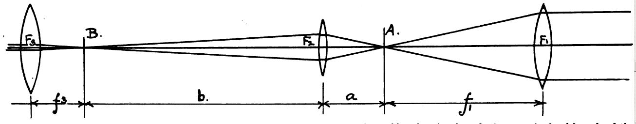
The figure represents the simplest form of
terrestrial telescope in which F1, is the objective F2
the erecting lens, and F3, the eyepiece. In practically
all rifle sights the distance a is less than b, and in this case
the image A formed by the objective is smaller than the image B
formed by the erecting lens. The erecting lens thus helps to
magnify the image. This ratio of b over al is called the inversion
ratio, and the total magnification of the telescope is equal to
the focal length f1 of the objective F, divided by the
focal length f3, of the eyepiece F3,
multiplied by the inversion ratio b over a. In the case of an
invert image telescope where there is no erecting lens, the
magnification is f1 divided by f3. In a
prismatic telescope the prisms simply erect the image but do not
magnify.
If we now study the formula for magnification
equals f1 divided by f3, multiplied by the ratio of b
to a, we can immediately see three possible ways to increase the
magnification. If f1 is increased the magnification
increases. If the ratio b to a can be increased the magnification
is increased, and lastly if f3 is made smaller, the
magnification increases.
There is still a fourth possibility, that of
using the same objective F1 but making its image larger
by placing a concave lens between F1 and A. The concave
lens then becomes a negative amplifier, and the resulting image A
formed by F1, and this negative or concave lens is
larger than if formed by F1 alone. In the case of the
prismatic and invert image or astronomical telescope, the only two
ways to increase the magnification is to increase f1,
or decrease f3. In using the different methods of
changing the magnification it is well to study their effect upon
the mechanical and optical properties of the sight.
In any optical instrument there is always a
definite relation between field and magnification. The apparent
field of view, is equal to the product of angular field and
magnification. If the magnification is increased the new field is
equal to the apparent field divided by the increased
magnification, the apparent field having remained constant. The
illumination is also dependent upon the magnification, and as
magnification increases illumination decreases as the square of
the increase of magnification. Eye relief and length of scope are
affected differently by the different methods and will be treated
separately under each method.
Increasing the magnification of a scope by
shortening the focus of the eyepiece entails the least change in
the construction of the scope. The focus of the eyepiece can be
shortened by making a new eye lens of shorter focus, or by adding
another lens to the eyepiece, making the focus of the compound
eyepiece shorter. If a new eye lens only is made, it is generally
necessary to shorten the scope, but where it is desired to make no
change in the scope proper, the best method is to add another lens
to the eyepiece. This method will shorten the eye relief and make
the cross wires appear heavier and will give best results only
when all lenses of the scope are achromatic. Where objective and
erecting lenses are not achromatic, the residual color errors
become magnified upon increasing the magnification to the point
where they may be quite objectionable.
To increase the magnification by increasing the
inversion ratio, it is necessary to move both eyepiece and
erecting lens. As the erecting lens is moved toward the objective,
the image point B moves further away from the objective and the
eyepiece must be moved out in order to focus on the image. If the
cross wires are at B, they must move with the eyepiece, but they
are not enlarged.
If the cross wires are located at A, they need
not be moved, but their apparent width will increase with
increasing magnification. To decrease magnification reverse the
motions.
Increasing magnification by this method will
decrease eye relief and increases the length of the scope. This
method gives best results only with achromatic lenses. The method
which gives most satisfactory results with scopes having
non-achromatic lenses, is to replace the objective with an
achromatic objective of longer focus. The increase in
magnification is directly proportional to the increase in focal
length of the objective.
The achromatic longer focus objective gives a
much clearer and more distinct image even at the higher power,
than the old non-achromatic objective This method will shorten eye
relief and lengthen the scope but will not affect the apparent
size of the cross wires. In scopes like the Stevens, where the
objective lens is a considerable distance from the end of the tube
a longer focus objective can be fitted with out increasing the
over all length of the scope.
The last method, which consists of placing a
negative lens inside the focus of the objective gives the same
results as the third method. The negative lens should be
achromatic to obtain best results.
Summarizing the different methods, the first
method has the most advantages, the change is readily made from
one magnification to another without changing the adjustment of
the scope and there are no alterations on the scope itself. The
lenses are readily available and can be made to give any
reasonable magnification. The other methods require the fitting to
be done by a skilled mechanic and optician and the change from one
magnification to another cannot be readily and quickly made.
SO much has been written by optical manufacturers about the danger
of touching the lenses in a telescope, or attempting to clean them
without sending them to the factory, that the average owner will use
his scope as long as it is at all possible to see through it, rather
than suffer the inconvenience of sending it to the maker for
cleaning. Using a scope in which the lenses are not thoroughly clean
is not conducive to the best results any more than using a dirty
rifle barrel.
The dissembling and cleaning of a telescopic sight or spotting scope
is a simple operation and there is no reason why any user can not do
this himself, providing he uses due care and attention to small
details.
The necessary tools are a small screwdriver, pencil and a large
sheet of clean paper, a large open vessel of alcohol, some clean
soft old linen and some soft tissue paper.
In taking the instrument apart, first remove the objective cell and
objective and sketch on the sheet of paper just exactly how it fits
into the instrument. In some makes of scopes the cell is only a
straight tube, putting it in wrong end first will cause no end of
trouble later. Whenever any cell or lens is removed, always mark the
end which is to be put in first, before laying them down. After you
have picked it up a few times you will probably have forgotten just
which end should be put in the tube first.
If the lens is spun in its cell do not at tempt to remove it, but
just clean it thoroughly with a soft linen rag moistened with
alcohol. Be sure to remove all greases from the cell and lens
surfaces and dry finally with the fine soft tissue paper. Any
remaining lint or dust should be blown off. If the lens is mounted
in the cell and held in by a threaded ring, it can readily be taken
out for cleaning. In removing the lens from its cell, care must be
exercised not to use force, and to have the lens come out perfectly
straight. If the lens becomes tilted in its cell very carefully
press from below on the lower side with a match stick, to straighten
it up before proceeding further. There is great danger in chipping a
lens when it becomes tilted in its cell, if much pressure is used,
and it must be carefully pushed straight before attempting to push
it out any further. An easy way to remove the lens from its cell is
to turn the cell over and tap it on a table top covered with clean
paper, and the lens will readily drop out squarely. Be sure to mark
the lens on the edge with a pencil so that it is put in right side
first. Only a lens with equal curves on front and back surfaces can
be reversed in its mounts without definition being entirely lost.
To assemble the lens in its cell again, take a clean soft pine stick
with a flat smooth end which will just go through the lens cell,
wrap tissue paper over the end of the stick, and drop the lens cell,
right side up, down over the stick. Set the clean lens on the fiat
end of the stick, and carefully bring the cell up to the lens and
lift the lens of the stick. A little shaking or tapping of the cell
will allow the lens to slide readily down into the cell as the stick
is withdrawn. In this manner the lens will set down squarely into
the cell without danger of becoming tilted and wedged. The retaining
ring can now be screwed down onto the lens and tightened just enough
to hold the lens without rattling. NEVER screw the ring down as
tightly as you can, as this will strain the lens and absolutely ruin
the clearness of the image, as well as produce cross parallax.
Having now thoroughly cleaned objective and cell, wrap it in tissue
paper and set aside until all the parts are cleaned.
The next operation is to remove the eyepiece and clean it thoroughly
and replace it in its cell. In scopes where the eyepiece and
erecting system are all enclosed in a long brass tube, the lenses,
diaphragms, separating rings and reticule can all be pushed out of
the tube and cleaned. In dissembling such an eyepiece, press on the
outside lens with a soft pine stick covered with tissue paper, and
cupped out in the center so that the stick bears only on the outer
margin of the lens and not in the center. Pressure on the center of
the lens may split it. Press the parts out very slowly and carefully
and mark each piece with a number and arrow to indicate which face
goes in first in assembling, and make a note and sketch of each.
With this precaution you will have no trouble, but if you depend on
memory you will have a game in assembling which will rival chess for
variety and difficulty.
The cross hairs should never be touched with anything whatever. Any
dust upon them should be removed by blowing on them and examining
them with one of the eyepiece lenses to see when they are clean.
After all optics and reticule are removed from the sight tube,
thoroughly clean it with alcohol to remove any grease, and push
several clean cloths through it, finally following by the use of
tissue paper. Any dust left in the tube or on the lenses will be
sure to drop on the lenses, due to shock of firing, and will
eventually get onto a lens where it is visible.
After all units are thoroughly cleaned, they can be put back into
the tube in their proper order, and the sight focused upon the
target for parallax, as described in my article in the May 1st
issue.
While glass is always considered exceedingly hard, still it is very
easily scratched or abraded and care must be exercised in handling
the highly polished surfaces of a lens. NEVER lay a lens face down
upon a table or box. Place it upon a clean piece of paper which has
been wiped off to remove any dust. The fine dust which settles on
everything contains a high percentage of silica, which will scratch
the hardest glass. A lens should always be very lightly wiped at
first to remove dust, then cleaned with a soft linen rag and
alcohol.. An old soft handkerchief is as good as anything which can
be used for cleaning lenses.
The above instructions for cleaning will apply to any telescope or
sight and with care no one should have any difficulty in cleaning
his telescope or rifle sight. There is no need for sending it to the
maker or an optician unless the lenses are tarnished or corroded.
This happens occasionally where they are exposed to salt water or
chemical fumes and in this case lenses will have to be re-polished
upon a lens grinding machine.
How to Make and Insert Cross
Wires and Post Reticules
By J. W. Fecker
ONE of the most vital parts of a telescopic sight
are the cross wires or other mark used to center the image in the
field. If they are not satisfactory, the entire value of the
instrument is lost, for its accuracy depends to a great extent upon
the clearness of these sighting marks, and their effect upon the
shooter's eye.
There is no sighting mark which can be universally
used. What is very well adapted for one particular shooter’s eye may
be most unsuitable for the next person who tries to use it. In like
manner, there is no sighting mark which is equally well adapted to
indoor target shooting, outdoor range shooting or hunting in a dim,
poorly lighted underbrush. For these reasons a shooter will often
find the standard factory reticule unsatisfactory and is often
tempted to try to change and make one to suit his own requirements,
especially when the factory can not supply him with what he desires.
He can readily do this if he has more than a little patience and is
not tempted to give up too easily.
There are various materials which can be used for
cross wires. Very fine wire can be had in copper, silver, platinum
and tungsten. In wire thinner than one thousandth of an inch
diameter, the copper, silver and platinum tends toward a crystalline
structure and is likely to break, when used on a rifle with heavy
recoil. Fine spun glass can also be used, but it is not as good as
metallic wire. Tungsten wire can be obtained as fine as one-quarter
of a thousandth of an inch in diameter, and it is remarkably strong.
The one thousandth tungsten wire will support 3 to 4 ounces without
breaking. Silk fibre and spider threads are very good for cross
wires. Spider threads are as elastic as rubber bands, and when
properly inserted will not shoot out on any rifle.
The spider threads are not those taken from the web of the spider,
but from its cocoon. Late in August and early in September the large
yellow field spider with a black cross on its back spins its cocoon
in the fields. It is most frequently found on golden rod and around
blackberry bushes. This cocoon is about three-quarters of an inch in
diameter and is a round brownish ball with a rather hard crust on
the out side. It should be cut open and thoroughly steamed to kill
the eggs inside. Between the egg sack and the outer shell is a fine
cushion of reddish down. This is the part to be used for cross
wires.
The tungsten wire can be obtained from any maker of incandescent
lamps. Fine silver and platinum wire can be obtained from Baker
& Co., Newark, N. J. .
The reticule cell should be thoroughly cleaned
before starting and should have the scores cut in for locating the
wire. If no scores are cut in the cell, they can be cut in the
following manner: Upon a large white sheet of paper, draw a circle
12 to 15 inches in diameter, and accurately lay off 4 points on
circumference exactly 90 degrees apart. Put a pin through’ each
point and stretch a fine thread over each pair of diametrically
opposite pins, so as to give you two fine threads exactly at right
angles to each other. Slip the reticule cell under these threads and
accurately center it under the intersection of the threads using
your eyepiece or other magnifier to set it as close as possible.
With a fine needle make a dot where each thread crosses the edge of
the cell, and take a very sharp knife and lay it diametrically
across each pair of these points and press down, so as to leave a
very fine sharp line across the cell. Use your magnifier freely to
see that the knife edge is exactly over each dot before you bear
down to cut the score. The scores should not be deeper than 0.003 to
0.005 inch.
In a factory where reticules are made, the reticule
is centered upon a stud, mounted on an index head, and the scores
are cut with a very fine dividing cutter and accurately indexed so
as to be exactly at right angles.
If spider line or silk fibre is to be used, first prepare two bent
wires, a long black hair pin is just the right weight, by putting a
small ball of beeswax on each end and spreading them so that the
distance between ends is about one-quarter inch greater than the
diameter of the reticule cell. With a long needle, pick out a loose
end of thread and take a hold of it, letting the cocoon hang down.
Wrap this end about 6 times around one waxed end of a wire, then
turn over the wire so that the thread comes over the other end of
the wire, and wind the thread around the other end about six times,
and pull off the cocoon. You will have a fine thread of spider silk,
firmly fastened to the two ends of the hairpin. It should now be
hung some distance over a small vessel of boiling water, so as to
steam the thread and make it absorb all the moisture it will hold.
If the thread is not steamed, it may slack up later on a damp warm
day. After the thread has been steamed 10 to 15 minutes, take the
hair pin by the back end, and slowly and carefully lay it over the
reticule cell so that the fine thread will fall as nearly as
possible in one pair of scores.
Allow the back end of the hairpin to rest on the table, but the two
open waxed ends should not touch the table. They must hang free,
supported by the thread laying across the reticule cell. If they
touch, place coins under the cell until the ends of the hairpin
hangs free. The weight of the hair pin puts just sufficient tension
in the thread.
With a magnifying glass and a long pointed needle push the thread
over until it drops into the scores. When it is in both scores,
place a very minute quantity of thin shellac or collodion in the
scores to stick the thread down. The less material you use to stick
the thread in with, the quicker and more securely it holds the
thread. A large drop of shellac will dry slowly, and contracting as
it dries, it will pull the thread with it until it breaks. The least
possible amount of shellac is the best. After ten minutes cut the
ends of the thread, and place a new piece on the hairpin and put it
in the other pair of scores.
Fastening the spider silk on the wire holder and
laying it in the scores requires a little practice and patience, so
do not be disappointed if you break the first dozen. Once you have
it cemented on and dried you will have the finest and most uniform
wire. This spider silk is about one ten thousandth of an inch in
thickness, and when properly focused in the eyepiece it is as black
and opaque as any heavy wire.
When using metallic wire, it should be soldered in the scores with a
jeweller’s blowpipe, and placed in tension, by hanging a small
weight on each end, the size of the weight depending upon the
strength of the wire.
Care must be exercised to heat only the point where the wire touches
the cell, very quickly, for if the entire cell becomes thoroughly
heated before the solder sets, the wires will be slack upon cooling.
Tungsten can not be soldered or brazed, and only
spot welded with great difficulty even with elaborate welding
apparatus. The only secure way to fasten it in place is to clamp it
under a washer, held down by a small watch screw. After the screws
are all turned down securely and the wire firmly held, put a little
shellac over the wire and screw-head as an added precaution. Mounted
thus tungsten wire will stand any shock. The only advantage tungsten
wire has over spider thread is that it can be obtained in a variety
of sizes, while spider thread is pretty uniform in thickness.
The making of a good post, either flat topped or pointed, is an
equally ticklish job. Post reticules are made of thin steel or hard
brass wire. The thickness depends upon the focus of the eyepiece.
For short focus eyepieces, which magnify highly 0.005 to 0.007 of an
inch, is about right. For long focus eyepieces with low
magnification, 0.010 to 0.015 of an inch gives best results.
The first operation is to thoroughly straighten the wire. Drive
about a dozen or fifteen 1 ½ inch nails into a board about
one-quarter inch apart and stagger them about one-sixteenth inch, as
shown in the sketch.
Wind the wire in and out around the nails and
slowly pull it through the row of nails. Repeat several times until
the wire is straight and free from kinks. A little soap is a good
lubricant for this operation. The alternate right and left bending
will straighten the wire. After thus straightening it, examine it
carefully with a magnifier and pick out a part which is particularly
smooth and of uniform diameter, and cut it out of the piece. If you
desire a square end post, clamp this wire firmly between two metal
plates with square ends, so that the wire just barely sticks out
beyond the plates, and using a very fine oil stone polish it down
until the stone has polished the ends of the two plates thoroughly.
Take the wire out and examine it with the magnifier. The end should
be perfectly flat and square, with sharp, clean-cut corners. If not
just right, place it between the plates again, and repolish the end.
The finer the oil stone and the lighter the pressure, the sharper
will be the square end on the post. With a little practice a very
nice post can be easily made.
A pointed post is rather difficult to make without a speed lathe and
a very small chuck. It can, however, be made by hand. To do this,
take two small, narrow strips of metal and cut a shallow V groove in
each, so that when placed together they will just clamp the wire
securely in the groove. The wire is thus held like the lead in a
pencil and holder and wire can be rubbed down to a sharp point, just
as one would grind down a pencil on a stone. Considerable skill is
required to produce a point which is sharp and uniformly round.
Having now made the post, the next step is to place it in the cell.
The score for the post should be cut deep enough so that the post is
half imbedded in the cell when it lays in the score. Then place the
horizontal wire in its scores and fasten it. The post can now be
laid in its score and the end allowed to rest upon the horizontal
wire. The post should be slid back and forth until the end projects
the desired amount above the horizontal wire. The post is now
clamped in position with two small watch screws, or can be soldered
with a blowpipe. The reticule should be carefully examined with a
magnifier when completed and any dust or lint blown off the wires. A
skillful operator can remove dust from a spider line with a sharp
needle, but this is more often disastrous than not. With a little
practice and patience, the average rifleman can soon achieve the
necessary dexterity to make for himself any reticule he may wish,
quickly and economically.