|
USE
ONLY THIS REFERENCE TO SERVICE YOUR
IBM MONITOR!
SHSA380053.BOO
PS/2 Display Hardware Maintenance Manual,Vol 1
|
2.5.2.4.5
Video Levels and Cutoff Voltages
All adjustments must be made with the brightness
control set at center detent and the contrast control set
at maximum. Select mode 4 (or mode 3 if not available) to
display the test patterns.
Video Card Potentiometer and
Control Layout
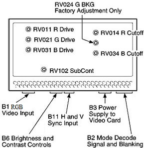
NOTE: Look at the
"Cutoff" and "BKG", it appears the older term was "Cutoff"
Background "BKG" is a term that makes sense, as "Drive" is
the upper strength of the color gun, while "Background" is
the lower limit of discernible color gun perception.
NOTE: The
potentiometers are laid out with "Drive" on the Left,
"BKG" on the Right.
NOTE: There appears to
be a typo, "B1" was shown as "B1 RGD", until I see some
documentation, I'll go with "RGB"
Adjust Color Gun Lower
Level [Background]
1. Select option 3, pattern C (Full Screen Raster), and press spacebar to get a black screen.
a. Set RV014 (R.BKG) and
RV034 (B.BKG) fully clockwise.
b. Adjust RV508 (G2) [on analog card] until a
background raster is just visible.
c. Adjust RV014 (R.BKG) so
raster is tinged red, readjust until red tinge just
disappears.
d. Adjust RV034 (B.BKG) so
raster is tinged blue, readjust until blue tinge just
disappears.
e. Adjust RV508 (G2) until background raster just
disappears. When background color point is correct, the
raster is white or gray until it disappears. If it is not,
repeat this step.
Adjust Color Gun Upper
Level [Drive]
2. Connect a voltmeter between ground (GND)
and ABL1 on connector D8.
Figure 8-13.
Connector D8
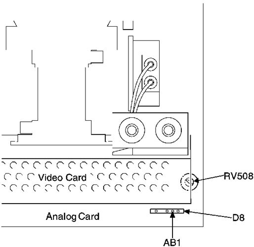
NOTE:
I've seen different depictions of RV508, this one shows
the adjustment screw pointing up.
3. Press
spacebar to get a full blue screen.
4. Adjust RV031 (B.DRIVE) to give:
(8517) -1.38 V dc.
(9517) -1.60 V dc.
5. Press spacebar to get a full green screen.
6. Adjust RV021 (G.DRIVE) to give:
(8517) -2.30 V dc.
(9517) -2.15 V dc.
7. Press spacebar to get a full red screen.
8. Adjust RV011 (R.DRIVE) to give:
(8517) -2.50 V dc.
(9517) -2.60 V dc.
9. Press PF3 to return to setup patterns. Option 2, pattern B (50 mm square white block).
10. Press spacebar to get a white block.
11. Adjust RV102 (SUB.CONT) to the highest voltage possible within the range:
(8517) -0.45 V dc to -0.50 V dc.
(9517) -0.50 V dc to -0.55 V dc.
12. If voltage is not within this range, repeat all previous steps for this procedure.
13. Press PF3 to return to setup patterns. Select option 4, pattern D (Gray Scale).
14. Check at max and min contrast that the blocks are evenly gradated from black through to white with no color tinges. If they are not, repeat this procedure.
15.
Do focus and convergence adjustments after this procedure.
Focus and Convergence Adjustments