9517 / 8517 Monitor Preliminary Steps

USE ONLY THIS REFERENCE TO SERVICE YOUR IBM MONITOR!

SHSA380053.BOO PS/2 Display Hardware Maintenance Manual,Vol 1


NOTE: This web page is INCOMPLETE, as it is restricted to 8517 / 9517 Specific Information. There are further safety procedures specific to the 9517 that are earlier in the Displays HMM.

I am not responsible for any outcomes of attempts to use any information on this page.

Review the High Voltage Discharge Procedure in section 1.3.4 of the PS/2 Display Hardware Maintenance Manual, Vol 1 [SA38-053-00 or -01].

If you are unfamiliar with safe adjustment of equipment that has voltages of 23KV, this is NOT the place to start! This includes using the proper insulated or non-conductive tools specified by IBM.

USE AT YOUR OWN RISK!

41G3307 PS/2 8517 and 9517 Color Displays HW Maint Ref Jul92
   Some updated / more complete information.

2.5.2.2.1 Preliminary Steps [Simple Issues] 


1. Insert Color Displays Test-Pattern Diskette in drive A of the system.

2. Power on system and display. System runs internal checks, loads program from diskette.

3. Allow 20 minutes for display to warm up before making any further adjustments.


"Adjustment Procedures" in topic 2.5.2.4 when adjustments are required.


"Display-Specific Removals and Replacements" in topic 2.5.1 for removal / replacement procedures


DANGER

! Use caution when making adjustments with the cover removed.
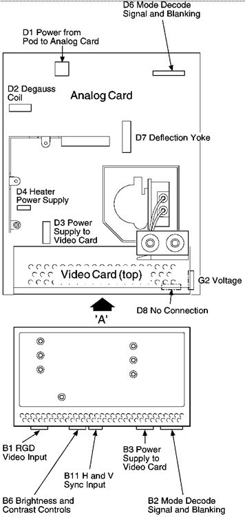
! There are high voltages on the analog and video cards


Symptom

Action

Displayed image width too large or too small
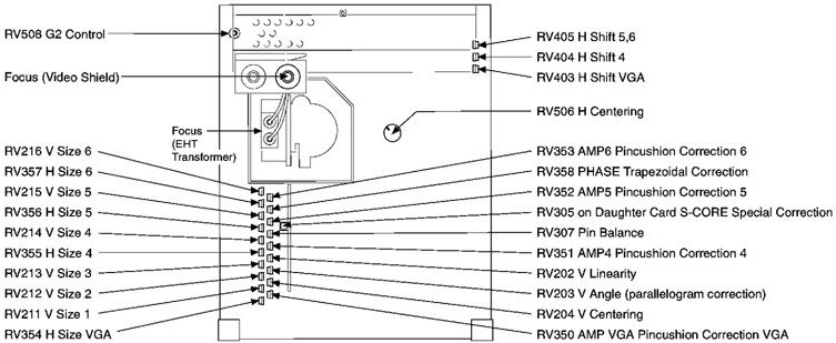
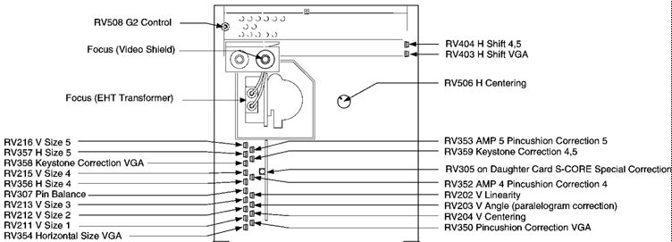
Adjust RV354, RV355 (8517 only), RV356, and RV357

- If symptom persists, replace analog card

Displayed image height too large or too small

Adjust RV211, RV212, RV213, RV214 (8517 only), RV215, and RV216

- If symptom persists, replace analog card

Contrast or brightness controls not working

Check connections between H3 (Fig 8-7) and B6 (Fig 8-11)

If good, do pod assembly checks

- Replace pod if it is defective

- Otherwise replace video card

Maximum or minimum white is poor

Video colorpoint is not set 

- Adjust as appropriate

Pattern is out of focus, vertical lines have colored edges or are multicolored

Do Focus and Convergence adjustments 

Geometry is poor

Follow Geometry Alignment procedures  

- If impossible, replace analog card

One or more colors missing

If colors good with test raster (signal cable disconnected), check connector B1 (Fig 8-11)

- Check connector on system unit

- If symptom persists replace signal cable

- If symptom still persists replace video card

Displayed image does not synchronize horizontally or vertically

Check connector on system unit. Ensure that D6, B2, and B11 are connected (Fig 8-11)

- If symptom persists replace analog card

- If symptom still persists replace video card

Background raster is not centered horizontally

Adjust RV506 (Fig 8-8 or Fig 8-9)

- If raster cannot be centered, replace analog card

Displayed image is not centered horizontally

8517, adjust RV403, RV404 and RV405 (Fig 8-8)

9517, adjust RV403, RV404 (Fig 8-9)

- If image cannot be centered, replace analog card

Displayed image is not centered vertically

Adjust RV204 (Fig 8-8 or Fig 8-9)

- If image cannot be centered, replace analog card

Displayed image height varies excessively between modes

Adjust RV211, RV212, RV213, RV214 (8517 only) and RV216

- If image cannot be centered, replace analog card