|
USE
ONLY THIS REFERENCE TO SERVICE YOUR
IBM MONITOR!
SHSA380053.BOO
PS/2 Display Hardware Maintenance Manual,Vol 1
|
H124719 9517 / 8517 MONITOR ALIGNMENT SERVICE AID
9517 MONITOR GEOMETRY ADJUSTMENTS:
PREFACE:
***********READ THE FOLLOWING COMMENTS CAREFULLY****************
Prior to using this procedure, it is STRONGLY recommended that you review RETAIN tip H12816 which is a Service Aid for PS/2 and ValuePoint CRT monitors. This will help you understand the alignment procedure. Retain tip H122146 concerned with Monitor "image tilt" is also very informative.
It is MANDATORY that you be familiar with safety procedures required for servicing CRT monitors.
****************************************************************
There are 23 separate adjustments to align geometry on the 9517 monitor. Some of the adjustments must be made in each separate mode. Example; Vertical Size for modes 1, 2, 3, 4, & 5. You must be certain that the correct potentiometer (pot) is being adjusted, because the adjustments are sequence sensitive and interactive. While 23 adjustments initially sounds very challenging, following this process will reduce it to a few easily understood procedures.
The Test Pattern Diskette provides menus for selecting required test patterns. The programs on diskette will automatically present all available modes (resolutions) which the monitor and attached video adapter are capable of providing. For example, a 9517 with an XGA-2 Adapter/A, will provide 4 modes with resolutions up to 1024 X 768 pixels interlaced or non-interlaced. (Will not provide all available modes on Valuepoint systems.)
ALL ADJUSTMENTS MUST BE MADE with MONITOR BRIGHTNESS CONTROL set at center detent and CONTRAST CONTROL must be set at MAXIMUM.*
* The brightness control detent is "soft" and may not be easily felt on some monitors. Carefully feel for it in the center of the control (The control on left is Brightness, the one next to the power switch is Contrast.).
Note: Provide at least 12 inches clearance from other monitors, florescent desk lamps, appliances or other electromagnetic devices, to minimize the influence of unwanted magnetic fields, which could make these adjustments difficult or impossible.
Use the plastic end of adjustment tool FRU P/N6247769 for geometry and focus adjustment procedures. The metal tipped end is used ONLY for adjusting the video card. Adjustments for unsupported modes are not required. However, if the monitor is later attached to an adapter which provides additional modes, further adjustments may be required. For instance, if monitor is aligned while attached to an XGA-2 adapter (4 modes) and is later attached to an Image Adapter/A (5 modes).
Boot the PS/2 Color Displays Test-Pattern Diskette (part 41G8502 form # S41G-3317).
****************************************************************
NOTE: No other "test pattern diskette" or customer software is supported for use in alignment of monitors. Customer operating systems, software applications and windowing programs are also NOT VALID to make monitor quality evaluations.
****************************************************************
Helpful hints:
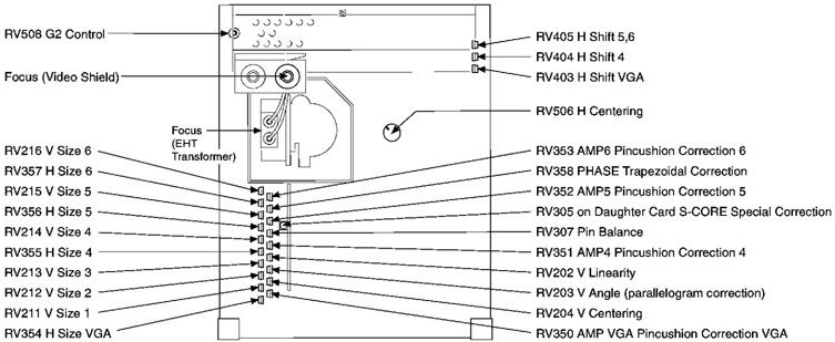
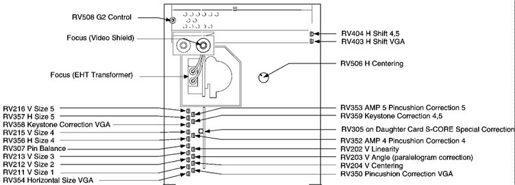
1. For convenience, copy and enlarge diagrams in section 8 of Monitor HMM, which show components and locations.
2. It is presumed that monitor Self Test functions correctly. A great deal can be learned about current alignment condition of a monitor by simply observing Self Test.
3. Don't spend too much time trying to "force" one adjustment to be correct or perfect. Move on to other adjustments and come back to it. Remember; adjustments are interactive!
START HERE:
MODE 4 Alignment Procedure:
1. Select mode 4 (or mode 3 if mode 4 is not available), then ENTER. Setup Patterns window will open.
2. Select option 3, pattern C - Full Screen Raster, then press ENTER. A full screen green raster will appear. Now press the space bar 4 times to get a black screen (a blue, red, white, then black full screen raster will appear).
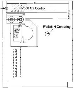
3. Adjust RV508 (G2) until the background raster is barely visible. The edges of raster can just be seen in dim room lighting. This adjustment will be "refined" later.
G2 is primary video brightness. Front panel brightness control is fine adjustment for it.
**********************************************************
Note: On new analog card FRU's, G2 is turned all the way down at the factory. This often results in no visible image (or raster) and is often perceived to be a new defective analog card FRU. Turning up G2 slightly should result in a visible raster.
**********************************************************
4. Adjust RV506 (H.CENT) until background raster is centered within bezel.
5. Now adjust RV508 (G2) again, until background raster just disappears.
6. Press F3 to return to Setup Patterns screen.
7. Select option 1, pattern A - Crosshatch. Press ENTER. A green crosshatch appears. (If it is not "true green," don't be concerned. This will be corrected later in the Color Point adjustment procedure.)
8. Center pattern horizontally within bezel.
|
Display |
Mode
4 |
Mode
3 |
|
RV405
H Shift 5,6 |
RV403 H Shift VGA |
|
|
RV404
H Shift 4,5 |
RV403
H Shift VGA |
9. Adjust RV204 (Vertical Centering)
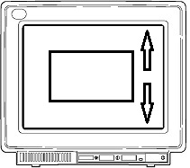
Pattern is centered vertically within bezel. (Use a plastic ruler to determine exact center of bezel).
10. Adjust Pattern Horizontal size
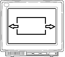
Distance between each vertical edge of pattern and bezel is:
5/16" (7.5 mm ± 0.5 mm) in mode 4
1/2" (11 mm ± 0.5 mm) in mode 3.
|
Display |
Mode
4 |
Mode
3 |
|
RV356
H Size 5 |
RV354
H Size VGA |
|
|
RV356
H Size 4 |
RV354
H Size VGA |
11. Adjust Pattern Vertical Size
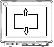
Distance between each horizontal edge of pattern and bezel is:
5/16" (7.5 mm ± 0.5 mm) in mode 4
1/2" (11 mm ± 0.5 mm) in mode 3
|
Display |
Mode
4 |
Mode
3 |
|
RV215
V Size 5 |
RV213
V Size 3 |
|
|
RV215
V Size 4 |
RV213
V Size 3 |
Notes: Use care and make sure you are adjusting correct pot in the next few steps. Refer to figure 8-12 on page 8 - 19 of Monitor HMM for illustrations of basic monitor geometry controls and resulting effects.
If one or more of the following adjustments doesn't seem to have enough control, move on to the others and come back to it later. Remember, these adjustments are interactive (they affect each other) and one or two of them may be "out" far enough to make others seem "ineffective."
12. Adjust RV202 V.LIN (Vertical Linearity)
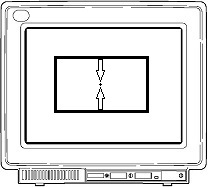
Distance between top and center lines of crosshatch pattern is same as distance between bottom and center lines of crosshatch pattern.
13. Adjust RV307 PIN.BAL (Pincushion Balance)
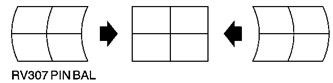
Center vertical line of crosshatch pattern is straight.
14. Adjust RV305 (S-CORE)
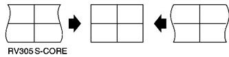
Vertical (left and right) edges of pattern are straight.
15. Adjust pincushion controls
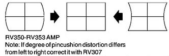
Vertical edges of pattern are straight.
|
Display |
Mode
4 |
Mode
3 |
|
RV352 AMP5 Pincushion
Correction 5 |
RV350 AMP VGA
Pincushion VGA |
|
|
RV352 AMP4 Pincushion
Correction 4 |
RV350 Pincushion
Correction VGA |
16. Adjust trapezoid controls
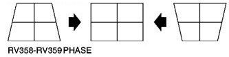
Edges of pattern are parallel.
|
Display |
Mode
4 |
Mode
3 |
|
RV358 PHASE Trapezoidal
Correction |
RV358 PHASE Trapezoidal
Correction |
|
|
RV359 Keystone
Correction 4,5 |
RV358 Keystone
Correction VGA |
17. Adjust RV203 V. ANGLE (Vertical Angle)
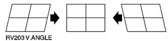
Edges of pattern are vertical.
18. It may be necessary to repeat steps 13 - 17, for RV307, RV305, RV352, RV359 and RV203. Because these adjustments interact with each other, adjust them for the best immediate result, then repeat them until the best overall geometry is achieved.
Mode 4 alignment is now complete. Continue alignment for Mode 5 if available, or skip to mode 3 and continue.
MODE 5 Alignment Procedure: (Image Adapter/A or equivalent required)
19. Press F3 to return to selection menu. Select Mode 5 and press ENTER.
20. Select 1. Pattern A - Crosshatch. Press ENTER; a green crosshatch pattern is visible. Press space bar 3 times for a white crosshatch pattern.
21. a. Adjust RV353.
Vertical edges of pattern are straight
B. Set H Size (RV357)
Distance between each vertical edge of pattern and bezel is
5/16" (7.5 mm ± .0.5 mm.)
C. Set V Size (RV216)
Distance between each horizontal edge of pattern and bezel is
5/16" (7.5 mm ± .0.5 mm).
This completes Mode 5 Alignment.
MODE 3 Alignment Procedure:
22. Press F3 to return to selection menu. Select Mode 3 and press ENTER.
23. Select 1. Pattern A - Crosshatch. Press ENTER; a green crosshatch pattern is visible. Press space bar 3 times for a white crosshatch pattern.
24. a. Adjust RV350 (VGA Pincushion Correction)
Vertical edges of pattern are straight.
B. Adjust RV354 (VGA Horizontal Size)
Distance between each vertical edge (side) of pattern and bezel is
1/2" (11 mm ± 0.5mm).
C. Adjust RV213 (Vertical Size, Mode 3)
Distance between each horizontal edge of pattern and bezel is
1/2" (11 mm ± 0.5mm).
This completes Mode 3 Alignment.
MODE 2 Alignment Procedure:
25. Press F3 to return to Setup Patterns.
26. Press ESC to return to selection menu.
27. Select mode 2 and press ENTER. Select option 1, pattern A- Crosshatch. Press Enter, Then Press space bar 3 times for a white crosshatch pattern.
28. Adjust RV212 (Mode 2 Vertical Size)
Distance between each horizontal edge of bezel and crosshatch pattern is
1/2" (11 mm ± 0.5 mm).
This completes the Mode 2 Alignment.
MODE 1 Alignment Procedure:
29. Press F3 to return to Setup Patterns.
30. Press ESC to return to Selection Menu.
31. Select mode 1. Press ENTER. Select option 1, pattern A- Crosshatch. Press ENTER. Press space bar 3 times for a white crosshatch pattern.
32. Adjust RV211 (Mode 1 Vertical Size)
Distance between outer edge of pattern and the bezel is 1/2" (11 mm ± 0.5 mm).
Note: If vertical height problems are still encountered, the following vertical adjustments should be repeated with a cross hatch pattern in the mode given.
RV215 - V. Size Mode 4
RV202 - V. Linearity Mode 4
RV204 - V. Centering Mode 4
RV216 - V. Size Mode 5
RV211 - V. Size Mode 1
RV212 - V. Size Mode 2
RV213 - V. Size Mode 3
33. Geometry Alignment is now complete, continue with focus and convergence adjustments as follows:
FOCUS and CONVERGENCE Alignment Procedure:
34. Press F3 to return to Setup Patterns. Select highest resolution mode available (mode 5 with Image Adapter/A, mode 4 with XGA-2, etc.)
35 Select Pattern A - Crosshatch and press ENTER. Press space bar 3 times for a white crosshatch.
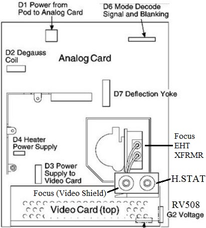
36. Adjust focus control mounted on bracket on video card for best focus of VERTICAL lines. (Control closest to neck of CRT.)
37. Adjust focus control ON THE SIDE of EHT transformer to focus HORIZONTAL lines (figure 8-9, page 8-14 of HMM)
38 Press F3 to return to Set Up Patterns. Select option 5, Pattern E - Focus Pattern and press Enter. Use this pattern and optimize adjustments in steps 36 and 37, for best overall focus settings.
39. Press F3 to return to Setup Patterns. Select option 1, Pattern A - Crosshatch and press ENTER. Press spacebar 3 times for a white crosshatch pattern.
40. Adjust H.STAT control on bracket on the video card (furthermost away from CRT neck) for best overall convergence. (Red Green and Blue all come together to form white lines.)
This completes Geometry and Focus Alignment. Continue with Colorpoint adjustments
COLORPOINT ALIGNMENT PROCEDURE:
Also referred to as, Video Levels and Cutoff Voltages:
ALL ADJUSTMENTS MUST BE MADE with Brightness Control set at center detent and Contrast Control set at MAXIMUM.
1. Select mode 4 (or mode 3 if mode 4 is not available), then press Enter key. The Setup Patterns window will open.
Select 3. Pattern C- Full Screen Raster, then press Enter. A full screen green raster will appear. Now press space bar 4 times to get a black screen (A blue, red, white, then black full screen raster will appear in sequence).
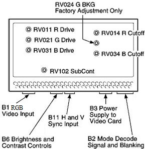
A. Using the metal tipped end of the adjustment tool*, Turn RV014, R.BKG (Red Background) and RV034, B.BKG (Blue Background), located on video card, fully clockwise.
B. Adjust RV508 (G2) until a background raster is visible, but not real bright, use dim room lighting if possible. (Note: G2 adjustment controls screen background brightness. The raster you see should be green, because of adjustments in prior step.)
Note: dimming room lights may help to determine when background raster disappears
C. Adjust RV014 R.BKG (Red Background) until raster has a red tinge, then readjust until red tinge just disappears. (raster now appears lighter; less green.)
D. Adjust RV034 (B.BKG) until raster has a blue tinge, then readjust until blue tinge just disappears. (raster now appears more white; dim white.)
E. Adjust RV508 (G2 Control) until background raster just disappears. When background color point is set correctly, raster is white or gray until it disappears. If it is not, repeat this step.
2. Connect voltmeter black (common) lead to ground (GND) and red (positive) lead to ABL1 on connector D8. (D8 is on analog card, just below corner of video card There is no cable attached. Page 8-21, figure 8-13 in the Display HMM shows this location.)
D8
___________ GND is second from the left and
| o o o o | ABL1 is the third from the left,
----------- as seen from the rear of the monitor.
3. Press space bar two times to get a full blue screen.
4. Adjust RV031 B.DRIVE (Blue Drive) to give:
(8517) -1.38 V dc. (All voltages in these
(9517) -1.60 V dc. steps are ± .03 Volt.)
5. Press space bar until you get a full green screen.
6. Adjust RV021 (G.DRIVE) to give:
(8517) -2.30 V dc.
(9517) -2.15 V dc.
7. Press space bar until you get a full red screen.
8. Adjust RV011 (R.DRIVE) to give:
(8517) -2.50 V dc.
(9517) -2.60 V dc.
9. Press PF3 to return to setup patterns. Select 2. Pattern B - 50 mm square block. Press Enter key.
10. Press space bar until you get a white block.
11. Measuring at D8, between GND and ABL1 (same as above), adjust RV102 SUB.CONT (Sub Contrast) to highest voltage possible within following range:
(8517) -0.45 V dc to -0.50 V dc.
(9517) -0.50 V dc to -0.55 V dc.
12. If voltage is not within this range, repeat steps 1 through 11 of this procedure.
13. Press PF3 to return to setup patterns. Select 4, Pattern D - Gray Scale. Press ENTER key.
14. While viewing gray scale pattern, turn front panel Contrast Control (beside power switch), from maximum all the way down through minimum contrast settings. Gray scale blocks should have an even gradient from black in upper left corner, through to bright white in center block, with no color tinges. Black block should be exactly same shade as black background. No lines should be visible separating black block from background (this proves that G2 is set correctly). If the check does not pass, repeat colorpoint adjustment procedure.
15. Repeat Focus and Convergence Adjustments after this procedure.
Notes: *
The metal tipped end of the tool should be CAREFULLY inserted into access holes in video card. The tip must go through another hole on circuit card, because adjustment potentiometers (pots) are mounted on backside of circuit board. Remove cover from rear of video card and examine how this is done.
A white crosshatch pattern is used during geometry and focus adjustments to provide a more intense electron beam to maximize interaction of beam magnetic field with magnetic field of deflection and focus coils (deflection yoke).
For best possible resolution, repeat all steps in this procedure, due to interactive nature of adjustments. Up to three complete passes through these adjustments may be required to satisfy critical graphics needs.