|
USE
ONLY THIS REFERENCE TO SERVICE YOUR
IBM MONITOR!
SHSA380053.BOO
PS/2 Display Hardware Maintenance Manual,Vol 1
|
| NOTE: This web page
is INCOMPLETE,
as it is restricted to 8517 / 9517 Specific
Information. There are further safety procedures
specific to the 9517 that are earlier in the
Displays HMM. I am not responsible for any outcomes of attempts to use any information on this page. Review the High Voltage Discharge Procedure in section 1.3.4 of the PS/2 Display Hardware Maintenance Manual, Vol 1 [SA38-053-00 or -01]. If you are unfamiliar with safe adjustment of equipment that has voltages of 23KV, this is NOT the place to start! This includes using the proper insulated or non-conductive tools specified by IBM. USE AT
YOUR OWN RISK!
|
When removing or replacing a CRT, you must discharge the High Voltage from the Anode to ground.
Note: Some CRTs contain a conductive coating on both the inside and outside surfaces to form a capacitor. Within some CRTs, a second capacitive charge builds up following the original discharge. It is therefore important to discharge each CRT a second time immediately before removal.
Sequence of Removing Power from Monitor
NOTE: Always turn the power on/off switch off first, then wait approximately five seconds before unplugging the power cord from the back of the display.
With the power cord connected, voltage may be present at the power supply card even with power switched off.
A static charge may be present at the line cord connector, at the rear of the display, if the line cord is disconnected before the power is switched off.
1.3.4 High Voltage Discharge Procedure [Remove / Replace CRT]
This section describes how to discharge high voltages from exposed display components.
|
DANGER
Hazardous voltages are present on the analog and
video cards.The extra high tension (EHT) voltage on the CRT anode cap exceeds 23 kV. Use extreme caution when working on the display with the power on and the covers removed. Some adjustments require you to place tools close to the EHT voltage. For safety and performance reasons, only plastic or insulated metal tools should be used. Remove all jewelry before starting any repair process. Never leave display unattended with covers removed. This applies whether or not the power cord is connected to the power outlet. With the power cord connected, voltage may be present at the power supply card even with power switched off. A static charge may be present at the line cord connector, at the rear of the display, if the line cord is disconnected before the power is switched off. Always turn the power on/off switch off first, then wait approximately five seconds before unplugging the power cord from the back of the display. Under fault conditions, a static charge can remain on the CRT anode long after the power cord has been disconnected. For this reason, it is important to discharge the CRT anode before disconnecting the anode lead. |
Before removing any CRT, discharge all stored potential that may exist on the CRTs anode button or base socket pins and the capacitor in the high-voltage supply. The procedures for discharging CRTs are explained in "High Voltage Discharge Procedure" as part of the steps in removal and replacement.
To avoid any shock hazard when working in the area of the high voltage anode lead, use the following to discharge the CRT to ground:
Screwdriver (part 1650855 or equivalent)
Jumper (part 7838690 or equivalent) with alligator clip (part 7838688 or equivalent) attached to each end; or Meter Lead Kit (part 6428104).
HV Discharge Procedure [Remove / Replace CRT]
Read the complete discharge procedure before starting; then continue in the order given.
1. Power off system and display, and disconnect all cables (see 1.1.3).
2. Remove tilt swivel stand.
3. Remove rear cover .
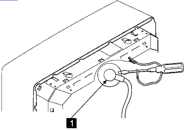
4. For display models 8517 and 9517, connect jumper between shield around the integrated tube component and the uninsulated part of the screwdriver shaft as shown in Figure 3-6. This will discharge the anode of the CRT 1 to the ITC shield (ground).
Figure 3-6. CRT Discharge Connection for 8517/9517 Displays
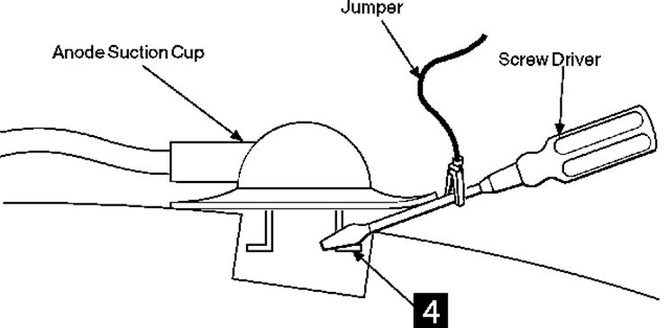
6. Do not touch any conductive parts when discharging high voltages. Insert the blade of the screwdriver under the suction cup until the end touches the anode lead connector 4 .
Figure 3-7. Discharge High Voltage to CRT Ground
7. Do this several times to ensure a complete discharge.
8. Carefully remove the anode suction cup from the CRT.
Note: Remove anode
suction cup immediately after discharge, to prevent CRT
capacitance from recharging.
If you are delayed for more than a minute or two,
perform discharge procedure again before removing CRT.
Note: Some CRTs
contain a conductive coating on both the inside and
outside surfaces to form a capacitor. Within some CRTs, a
second capacitive charge builds up following the original
discharge. It is therefore important to discharge each CRT
a second time immediately before removal.