IBM PS/2 Server 295: New
Thresholds for Client/Server Networking
IBM Personal Systems Technical Solutions, JULY 1992 Pages 5-13
By Mike Engelberg
Mike Engelberg
The TDA Group
Los Altos, California
IBM's new PS/2® Server 295 answers LAN users' demands for high reliability, data integrity, high performance, and fault tolerance in an application database server. Sophisticated technologies implemented in the PS/2 Server 295 make it extremely reliable and suitable for use in mission critical environments such as banking, public utilities, securities trading, and airline reservations. Software in the PS/2 Server 295 enables administrators to manage system resources from central locations, eliminating the need to have technical experts at each location on a network.

The new PS/2 Server 295 has much to offer users. Consider these impressive facts:
• Mass storage devices whose Mean Time Between Failure (MTBF) is expected to be at least 18 years and up to more than 40 years
• A server that keeps functioning even if a hardware component fails, and whose storage devices can be replaced while the computer is running
• A logical array of storage devices, across multiple Small Computer Systems Interface (SCSI) buses, which can protect data against failure of any component- even power supplies
• Fault tolerance that logically disconnects a failing component and switches to other working components and to spare components if installed - all without human intervention
• A hierarchical bus architecture that features dual Micro Channel® expansion buses and a 64-bit, 200 MB per second main bus where up to eight specialized processors are attached - for application processing, data file and network transactions, data movement within memory, and system control and maintenance
• Up to four SCSI bus channels, each with its own disk processor, that control up to 28 GB of total storage
• Up to two 32-bit, 20 MB per second Micro Channel computing subsystems that feature Intel® 80486 cached processors, configured as tightly coupled microprocessors, running at either 33 MHz or 50 MHz
• Up to twelve slots for Micro Channel adapters and busmaster cards, including multiple Local Area Network (LAN) attachments
• Up to 128 MB of Error Checking and Correction (ECC) high-speed memory in an independent subsystem controlled by a 64-bit memory processor
• Optional Uninterruptible Power Supply (UPS) and optional redundant power supply
• A separate maintenance processor, with battery backup, that monitors system activity and usage; detects, logs, and highlights system errors; and enables a remote system administrator to tune and reconfigure the server system
• Interactive software, running as an OS/2® application, which provides the remote system administrator with instantaneous status reports about the overall server system, and also the ability to ask for detailed reports about system components and environmental settings
• Full compatibility with major industry standards, including IBM's Systems Application Architecture® (SAA™); networking architectures such as IBM's Systems Network Architecture (SNA); operating systems such as OS/2; graphical user interfaces such as the OS/2 Workplace Shell; and LAN managers such as OS/2 LAN Server
• An application database server system that protects users ' investments when they add to it at a later date How many computer systems does it take to provide all this? Now, just one - and what a computer it is!
Introducing the IBM Personal System/2 Server 295
The IBM Personal System/2® Server 295 is the first member of the PS/2 family to offer multiprocessing, fault tolerance, and administration from other locations.
Designed for mission-critical database applications that run in client/server network environments, the IBM PS/2 Server 295 is the first product of a long-term alliance between IBM and Parallan™ Computer, Inc. Under the terms of this alliance, IBM has exclusive rights to manufacture and market Parallan 's award-winning application server technology, while Parallan continues to develop advanced technology for client/server computing.
Client/Server Computing
Client/server computing is an architectural model that takes the greatest advantage of each component on a computer network - the central server and the remote (client) computers. In client/server computing, an application is divided between an application database server and client computers. Clients request data that is stored on the server, receive that data, and further process it; the server performs functions that require large amounts of storage, memory, file processing, transmission, and data security.
Client/server networks require powerful, reliable, secure server systems. The degree to which the PS/2 Server 295 responds to these requirements makes it suitable as the server in a network that handles mission-critical applications, such as public utility service and timely transaction processing.
Typical Applications
Enterprises use client/server computing in applications such as relational database management; communications and electronic mail; financial spreadsheets; word processing and desktop publishing; and groupware, in which diverse users contribute to the design and development of a common project. The following are examples of software products that currently run on the PS/2 Server 295:
• Ellipse™, an online transaction processor
• Selected Dun & Bradstreet® financial packages
• Lotus Notes®, a groupware application
• IBM Database Manager and Microsoft® SQL Server, database management systems
• IBM OS/2 Communications Manager
• PeopleSoft® Human Resource Management System
• OmniDesk™, an image management system
• TOPIC Real-Time, an information retrieval system
The PS/2 Server 295 is an open system; that is, its operating system is not proprietary. All applications developed to run under OS/2 will run on the PS/2 Server 295.
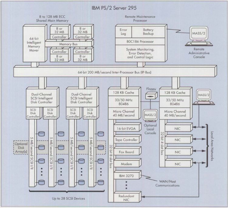
Figure 1. PS/2 Server 295 Architecture
Architectural Overview
Figure 1 gives an overview of the architecture of a fully configured PS/2 Server 295. The basis of the entire architecture is the 64-bit InterProcessor (IP) Bus with its incredible traffic capacity - 200 MB per second. With this capacity, the IP Bus is the major traffic artery within the entire system, linking all the specialized subsystems: computing, memory, mass storage, and maintenance.
Although the IP Bus is standard in all PS/2 Server 295 systems, all the subsystems except maintenance have configuration options. Enterprises can order their PS/2 Server 295 systems in configurations designed to meet their specific needs. The PS/2 Server 295's modular design enables enterprises to add resources as their needs grow. Figure 2 lists the available configuration options within each subsystem.
Figure 2. IBM PS/2 Server 295 Configuration Options
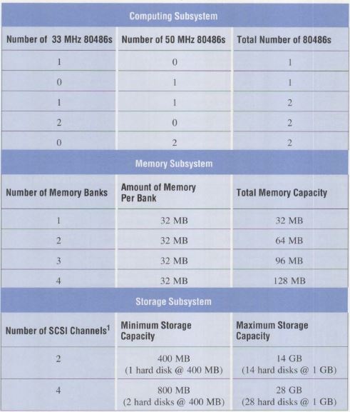
PS/2 Server 295 systems are built to order. Enterprises can order PS/2 Server 295 systems in any configuration that is within the minimum and maximum limits shown in Figure 2. Other components are also available, such as network adapters, high-speed tape backup devices, modems, and fax adapters. IBM will install and test all components ordered. IBM software - OS/2 and the Maximum Availability and Support System/2 (MASS/2) - is standard with all configurations, and is preloaded before delivery.
Computing Subsystems
In the lower right quadrant of Figure 1 are two complete computing subsystems. In a two-processor computing environment, the processors are configured as multiprocessors, capable of performing simultaneous operations.
The 33 MHz and 50 MHz processors come with an 8 KB cache on the processor chip itself. The 33 MHz processor has a 128 KB, zero-wait state secondary cache; the 50 MHz processor has a 256 KB, zero-wait secondary cache.
In PS/2 Server 295 configurations with one computing subsystem, the "computer" is the one on the left in Figure 1 - the one whose Micro Channel bus has eight slots (for seven 32-bit adapters and one 16-bit adapter). This bus can accommodate adapters for computer components such as display controllers, communication controllers, and Network Interface Controllers (NICs).
In configurations with two computing subsystems, the second (rightmost) subsystem provides four additional slots, for a total of twelve Micro Channel slots. In Figure 1, the four additional slots are devoted to network interface controllers (token ring, Ethernet™, and so on) for four local area networks. This architecture places faster network adapters on one Micro Channel bus and slower application adapters on the other, so that the slower adapters do not degrade overall system performance. Notice that there is a redundant NIC in the last slot of the first Micro Channel bus. System administrators can configure the PS/2 Server 295 so that the most critical LANs can be redundantly attached to the first Micro Channel subsystem to ensure continued up-time in case the primary subsystem has problems.
In Figure 1, the eight-slot Micro Channel subsystem is configured as the Application Processor (AP) and the four-slot Micro Channel subsystem as the File Processor (FP). System administrators have the option of configuring the eight-slot subsystem as the FP and the four-slot subsystem as the AP.
Memory Subsystem
The upper left quadrant of Figure 1 shows the PS/2 Server 295 's memory subsystem. Memory is accessed through a 64-bit high-speed interface to improve performance. The memory itself is 80 ns ECC page-mode memory. It has up to four memory banks, each with 32 MB of memory, for a total of 128 MB. Each memory bank has its own independent memory controller that performs concurrent memory bank accessing.
NOTE: The IPB Memory Board has 4x banks of 8x 30-pin SIMMs. These 30-pin SIMMs are parity, but the ECC function is performed on the IPB Memory Board by the 49C460CJ 32-bit CMOS Error Detection and Correction Unit, which is also used in the 7568-D40 GEARBOX.
Disk Controller Subsystems
The lower left quadrant of Figure 1 has two RISC-based SCSI disk processors called Intelligent Disk Controllers (IDCs). Each IDC has two SCSI channels, for a total of four SCSI channels. (The minimum configuration has a single IDC with two SCSI channels.) Each channel is capable of transferring data at the rate of 5 MB per second; all four channels can handle a total of 20 MB of data per second. Each channel has its own SCSI disk controller and up to seven attached devices. The devices can be either 400 MB or 1 GB SCSI hard disk drives. When all four SCSI channels are fully populated with 1 GB disks, the IBM PS/2 Server 295 has 28 GB of mass storage. Figure 1 shows a shaded area called Disk Arrays that crosses all four SCSI disk buses. This is one primary fault tolerance feature of the PS/2 Server
295, and will be discussed later.
NOTE: The system might look for text strings from the 0661 [400MB] or the 0663 [1GB] IBM drives.
Remote Maintenance Subsystem
The final processor component of the PS/2 Server 295 is the Remote Maintenance Processor (RMP) subsystem, shown in the upper right quadrant of Figure 1. This processor is an 80186 with 128 KB of Static RAM (SRAM) and a 256 KB Erasable Programmable Read-Only Memory (EPROM). The major purposes of this processor are to enable a system administrator - who may be at a remote location - to monitor, tune, and control the PS/2 Server 295 without affecting its throughput, and to track and log problems that may occur in the system. To make the problem log available when the system's power is disabled, the RMP subsystem includes a nickel-cadmium rechargeable backup battery with a life of up to 15 hours without recharging.
Figure 3. Cutaway View of PS/2 Server 295
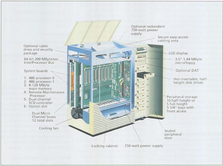
Storage Devices and Enclosures
Figure 3 shows a cutaway view of the PS/2 Server 295. Its physical enclosure is divided into two major parts: the system enclosure for buses and circuit boards, and the storage enclosure. The configuration shown 5 has room for 9 half-height disk drives, diskette drives, or Digital Audio Tape (DAT) drives. To attain the maximum of 28 drives, three more storage enclosures can be attached. Storage enclosures have a solid front door that keeps dust out of the drives. Within the main enclosure, air coming in is filtered before being circulated. Some physical security devices available for cabinetry and for the cables inside are shown in Figure 3. The storage enclosure that comes with the PS/2 Server 295 accommodates 9 devices. If a PS/2 Server 295 configuration has 10 to 19 storage devices, a second storage enclosure is required; if a configuration has 20 to 28 storage devices, a third storage enclosure is required.
Reserved Memory Manager
The PS/2 Server 295 's Reserved Memory Manager (RMM) enables application programs to access all the available memory. An application, therefore, can access and use as much as 128 MB of memory. This greatly enhances the performance of applications that heavily use memory, such as database programs. Those applications can take advantage of large amounts of main memory directly or through large virtual RAM drives.
NOTE: The RMM -MIGHT- have been needed on OS/2 1.3 installations, probably not for OS/2 ver 2.1
Fault Tolerance Features
The PS/2 Server 295 sets new heights of fault tolerance in client/server environments. Advances in hardware technology and software capability give the PS/2 Server 295 a level of fault tolerance not previously available in a client/server network environment. The list of fault tolerance features includes the following:
• MASS/2 software
• Remote Maintenance Processor
• Online spare storage devices
• Orthogonal RAID-5 Disk Array/2
• Dual 80486 processing subsystems
• Dual Micro Channel buses
• Up to two dual SCSI buses
• Parity checking on all buses in the system
• ECC memory
• An optional UPS and redundant power supply
Two of these features - MASS/2 and Orthogonal RAID-5 Disk Array - are significant advances.
Maximum Availability and Support Subsystem/2
The MASS/2 software is a set of tools for monitoring, tuning, and controlling PS/2 Server 295 systems from local or remote locations. Together with the PS/2 Server 295's fault-tolerant hardware technology, MASS/2 enables PS/2 Server 295 systems to recover from failures and to continue to run - all without the intervention of the system administrator. MASS/2 is easy to use, and it runs without affecting the performance of the server system.
Briefly, MASS/2 provides these functions:
• Monitoring and control of resource utilization
• Configuration management from remote locations
• Establishment of thresholds for continued operation of the system and for alarms
• System problem notification when attention is necessary
• Battery access to system trace logs in case of power outage
MASS/2 runs on the Remote Maintenance Processor discussed earlier. MASS/2 tracks hardware and network problems, notifies the administrator whenever a problem occurs, and enters the problem information into a log kept in the RMP subsystem. Because the RMP has battery backup, the administrator can access the problem log even when power to the system is disabled.
As shown in Figure 1, MASS/2 can be run in several locations. In the upper right corner of Figure 1, a remote terminal running MASS/2 is connected to the RMP over a communications line. Figure 1 also shows that MASS/2 can be run from a monitor attached to a client on a LAN, or from a monitor attached locally to the 80486 computing subsystems. This flexibility enables the system administrator to be located at a remote site and to control several PS/2 Server 295 systems from that site.
Figure 4. MASS/2 Monitor Screen
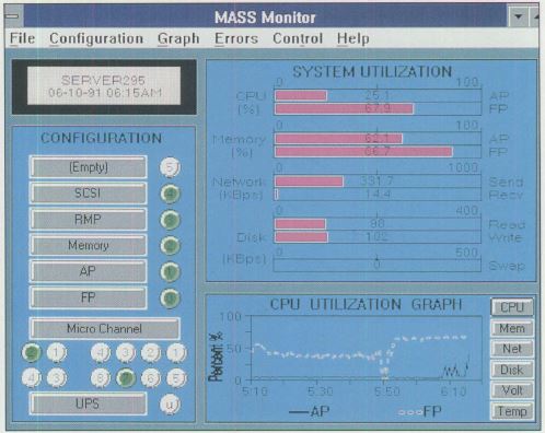
MASS/2 Monitor Screen:
Figure 4 shows the MASS/2 Monitor screen. This screen can be displayed on monitors attached to the PS/2 Server 295, to a client on a LAN, or to a remote computer that uses a modem to connect to the server. From the MASS/2 Monitor screen, a single system administrator can manage many PS/2 Server 295 computers located in several different places. Figure 4 displays, in graphic form, the overall status of all subsystems in a PS/2 Server 295. At a glance, the system administrator can see what is happening in a server system. The administrator can bring up additional information about any single component.
The left side of the MASS/2 Monitor screen shows the processors that are attached to the IP Bus. IP Bus slot 0 has the first of two 80486 computing subsystems, labeled FP; slot 1 has the second 80486, labeled AP. Slot 2 contains the memory processor; slot 3 has the Remote Maintenance Processor; and slot 4 has a SCSI channel processor. Slot 5, which is empty, is reserved for the second dual-channel SCSI processor.
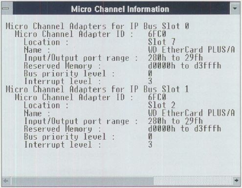
In the lower left corner are twelve buttons indicating the twelve slots on the 80486 Micro Channel subsystem buses. The FP is the one with eight slots; the AP has four. Notice that button 7 in the FP subsystem and button 2 in the AP subsystem are highlighted. This means the administrator is requesting detailed information about the adapters in those slots. The screen that displays the detailed information is shown in Figure 5.
Figure 5. MASS/2 Micro Channel Adapter Information Screen
If an optional UPS is installed in the PS/2 Server 295, its status is shown in the lower left comer of Figure 4.
The upper right quadrant of Figure 4 displays real-time statistics and bar charts of the utilization of all major subsystems. In the lower right quadrant, the administrator can select the subsystem and display the history of that subsystem's utilization during the past hour. (The subsystem shown in Figure 4 is the dual 80486 computing subsystem.) The hourly statistics are saved on disk for subsequent analysis. These statistics are useful for tuning the system configuration. The administrator can tell from the utilization statistics whether a subsystem's usage is heavy or light, and can therefore determine which subsystems have excess capacity and which need more resources.
Figure 6. MASS/2 Autodial Error Screen
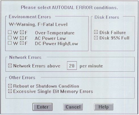
Warning Thresholds:
MASS/2 maintains system warning thresholds that the administrator can set. MASS/2 will then notify the administrator if the limits are exceeded. Figure 6 shows the Autodial Error screen, which contains several categories of potential system errors. MASS/2 sends a warning to the system administrator whenever a threshold for a selected item is exceeded. The administrator can then take appropriate action to notify users, to shut down the system if necessary, or to request maintenance. Usually the administrator need not take action, because MASS/2 has already interceded to keep the system running.
Soft Shutdown and Reboot:
If a hardware component or an application program fails, the PS/2 Server 295 system and the MASS software work in tandem to ensure minimal impact on continued operation. The server system has built-in diagnostics that can identify a faulty hardware component and logically disconnect it from the system. The server can also sense, through timers, when a program freezes or aborts. MASS/2 steps in to bring the remaining programs and file systems to a "soft" conclusion, reconfigure around the failed component, reboot the system, and restart programs and file systems at the point where they were stopped.
Security:
MASS/2 has a multi-level security system that restricts and tracks access to PS/2 Server 295 computers. Passwords protect access to the functions provided by MASS/2. The main administrator can give other people access to certain control functions. MASS/2 notifies the administrator whenever anyone else attempts to shut down or reboot a PS/2 Server 295.
More Control, Higher Levels of Support, Fewer Resources:
With MASS/2, system administrators enjoy a level of control not previously available. MASS/2 has a remote console feature that enables administrators to control and manage, from a central location, multiple PS/2 Server 295 computers that are installed at several remote locations. Centrally located administrators can see the utilization statistics and operational status of each server system, respond to error conditions on each server, control the distribution and installation of software updates for each system, and schedule maintenance for each server.
This wide span of administrative control, in combination with the PS/2 Server 295's capability of recovering from error conditions, means that enterprises can now have client/server environments at remote locations without also needing administrative and technical experts at those locations.
Spare Storage Devices
Another major fault tolerance feature of the PS/2 Server 295 is its implementation of spare storage. Any disk drive in a storage array can be configured as a spare. A spare storage device is used only to substitute for another device that has problems.
Whenever the PS/2 Server 295 senses that a storage device is failing, it activates a spare device, reconfigures the array, and activates the spare in place of the failing device. All this is done with minimum impact on the overall performance of the server system, and with no intervention by the system administrator.
When a storage device goes down, MASS/2 notifies the system administrator. The administrator can then request replacement of that device. Notice that all this time the LAN is up and running. In Figure 3, the storage device in the fourth slot down is labeled "hot-insertable." This means that the service technician can remove the faulty device and insert a new one while the PS/2 Server 295 is up and running. The new storage device becomes the spare.
Spare storage devices are included in the maximum number of 7 devices per channel or 28 devices per PS/2 Server 295 system.
Orthogonal RAID-5 Disk Array/2 Software
One element in Figure 1 is left to discuss: the shaded area in the lower left corner, labeled "Disk Arrays." The Orthogonal RAID-5 (Redundant Array of Inexpensive Disks) Disk Array/2 software is a major fault tolerance feature that enables the PS/2 Server 295 to protect against failure of any kind of component, even the power supply.
Typically, logical arrays are set up on a single SCSI bus, and consist of several storage devices and a single dedicated parity device to aid in the reconstruction of data if necessary. Having only one parity device constrains the overall performance of the devices in the array, which in turn slows the entire server. RAID-5 distributes the parity information among all the devices in the logical array. Parity writes occur simultaneously with data access. Spreading the parity information among all devices in an array ensures performance and data reliability.
Figure 7. Orthogonal RAID-5 Disk Array Concept
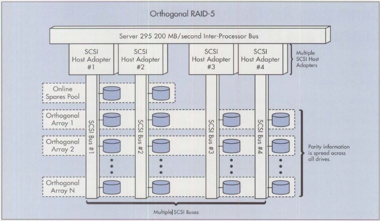
Orthogonality takes the RAID array concept a step farther. Logical arrays are set up to span multiple SCSI buses, as shown in Figure 7. Each SCSI bus has its own processor that accesses data. By multiplexing data access activity across four SCSI processors, the Orthogonal RAID-5 concept significantly improves data access performance.
Each disk array can have from 2 to 16 storage devices, and there can be multiple arrays, adding to the overall performance of the storage subsystem.
An important benefit of the orthogonality concept is reliable system recovery. Suppose either a storage device or a SCSI bus fails. Making calculations based on the parity data that is spread across all the SCSI buses, Disk Array/2 recreates the data that is on the faulty device, writes that data onto a spare device, and makes that device active within the array. All this takes place while the PS/2 Server 295 keeps running.
Because it encompasses multiple SCSI channels and storage devices, the Disk Array/2 software insures that server performance will continue if any of these components fails. Software and hardware logic reroutes data-access requests to alternate storage devices, as mentioned above, and to alternate SCSI channels. If an active storage device is on a channel whose SCSI controller fails, that device is removed from its disk array. The Disk Array/2 software then reconstructs the contents of that "missing" device as follows:
If a spare device is available, the following occurs:
• Disk Array/2 reconfigures the disk array to include the spare device.
• Using parity information that is spread among the remaining devices in the array, Disk Array/2 reconstructs the "missing" data on the spare device.
If no spare device exists, the Disk Array/2 software continues to dynamically reconstruct data requested from the "missing" drive. Note that data requested from all other drives continues to be available without any performance penalty.
Mike Engelberg is a 26-year veteran of IBM who is now an editorial consultant. While with IBM, he was an applications programmer and the editor of several technical newsletters and magazines about the IBM Personal Computer and Personal System/2 families and their software. He has a BS in mathematical statistics from the University of Chicago and an MBA from the University of Illinois.