Testing Model 90 Power
Supply
Measure Voltages with / without Connecting to Planar?
The Power Supply [through connectors P1/P2] provides part of the power distribution system for the Model 90. The planar board [through edge connectors J25/J26] provides the other part.
Peter Wendt says:
"Testing the PSU with the board attached may fail due to shorts or defects on the board. I always test it both ways: first with nothing attached, then with the planar. That's why I asked (in the 90 PSU thread) if it was tested detached.
Everything with a PS/2 PSU AFAIR is no-load operational. Old XT and AT aren't. The IBM 5170 AT01 with no HD came with a dummy load installed that somehow emulated the additional load of a harddisk to prevent the PSU from overshooting during power up / stabilization. "
Planars with failing buffer capacitors, failing MCA adapters, or various collections of grime and actual physical damage, may short or trigger thermal shutdown.
Testing voltages with J25/J26 connected shows how the PSU -AND- planar are doing, but NOT the status of the PSU by itself.
There is NO reason that a PSU needs to be connected to the planar in order to test the voltages on P1/P2, since PS/2 power supplies will stabilize WITHOUT any external load.
NOTE: P1 Pin 1 "GND" [Black] and P2 Pin 1 "-12V DC" [Orange] have the same relative position at the right hand of the connector, BUT they are NOT the same...
Connecting Test Leads
Note the (+) and (-) on each illustration. Read, Believe, Obey! When there are multiple wires for a voltage, they are tied together, and testing a like-colored wire will give the same results.
NOTE: Pay attention to the "- Lead Pin" and the "+ Lead Pin" when connecting your test leads. Swapping (+) and (-) might give you erroneous results.
Testing the +5V DC Lines
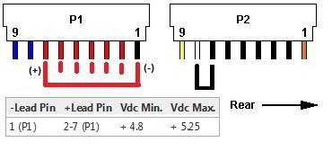
Short P2 Pin 8 "Power ON/OFF" [White] to P2 Pin 7 "GND" [Black]. This is a 5v sense voltage, nothing dangerous here.
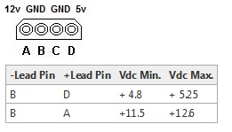
Measure from P1 Pin 1 "GND" [Black] to P1 Pin 7 thru Pin 2 "+5V DC" [Red]. Pins 7 - 2 are connected, so they should all be outputting the same voltage.
Testing the +12V DC Lines
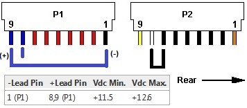
Short P2 Pin 8 "Power ON/OFF" [White] to P2 Pin 7 "GND" [Black]. This is a 5v sense voltage, nothing dangerous here.
Measure from P1 Pin 1 "GND" [Black] to P1 Pin 8 -OR- Pin 9 "+12V DC" [Blue]. Pins 8 - 9 are connected, so they should all be outputting the same voltage.
Testing the -12V DC Line
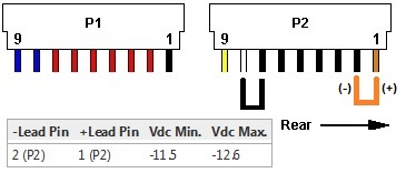
Short P2 Pin 8 "Power ON/OFF" [White] to P2 Pin 7 "GND" [Black]. This is a 5v sense voltage, nothing dangerous here.
Measure from P2 Pin 2 "GND" [Black] to P2 Pin 1 "-12V DC" [Orange].
Testing the Power Good Line
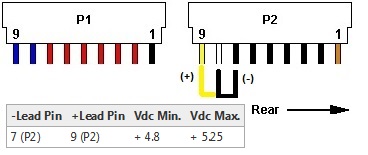
Short P2 Pin 8 "Power ON/OFF" [White] to P2 Pin 7 "GND" [Black]. This is a 5v sense voltage, nothing dangerous here.
Measure from P2 Pin 7 "GND" [Black] to P2 Pin 9 "Power Good" [Yellow]. Power Good will output +5V if all primary voltages are stabilized
Testing the Drive Power Lines
The Model 90's non-detachable drive power cables use Blue/Black/Black/Red.
Drive Power Cable Conductor Colors
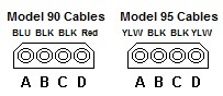
The relative positions of the +5v, +12v, and GNDs in the housing DO NOT CHANGE from the Model 90 to the Model 95 drive power cables.
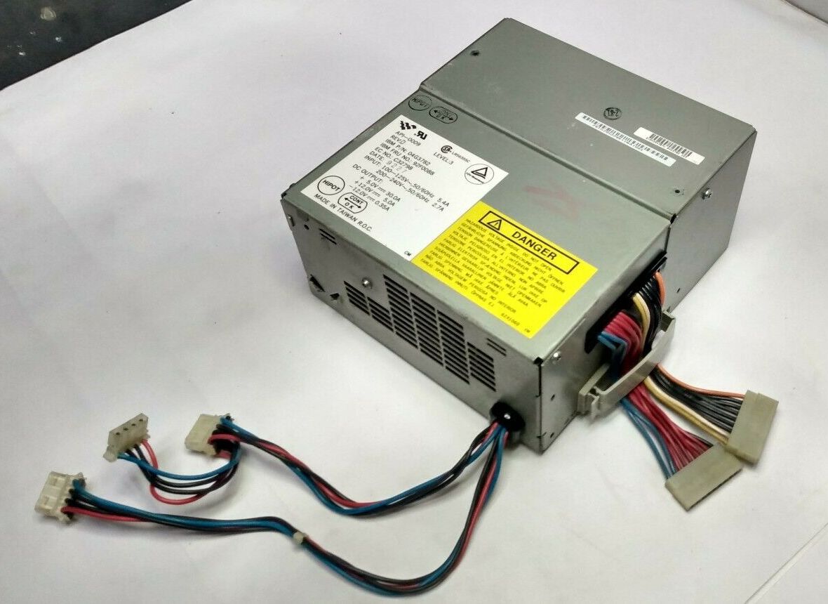
AcBel API-0009, REV B
Sometimes you will encounter a Model 90 PSU with short internal device power cables. A common "fix" is to use detachable Model 95 drive power cables to extend Model 90 drive power cables. IBM decided that Model 95 detachable drive power cables would use Yellow/Black/Black/Yellow for "reasons".
Short cabled PSUs have FEMALE receptacles
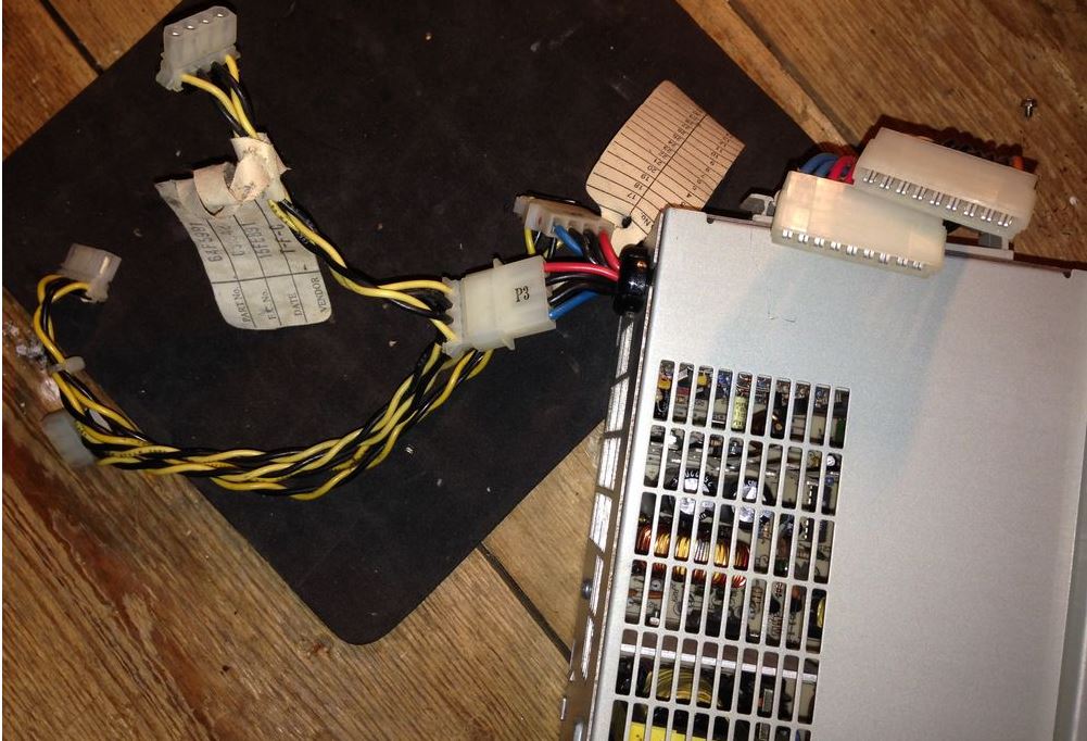
AcBel API-0009, REV D
Long cabled PSUs have MALE plugs.