by Brett Glass
Byte, vol 14 No 2, Feb 1989 pages 349-353
The interface you pick can dramatically affect your system's performance
Nowadays, many microcomputer manufacturers' performance claims center around hard disk drive interfaces and the encoding schemes they use- usually described by acronyms like RLL (run length limited), ESDI (enhanced small device interface), and SCSI (small computer system interface). How do these interfaces work, and what effects do they really have on performance? In this installment of Under the Hood, I'll describe some of the most popular interfaces for microcomputer hard disk drives and explain what "you can expect from each one.
The Big Picture
To get the right perspective on these interfaces, it's important to see how hard disk drives fit into the larger scheme of things. Figure I shows the full range of interfaces, from the low-end ST506 (used on the IBM PC XT and AT, among others) to the fast, powerful, and expensive IPI (intelligent peripheral interface) used on many mainframes.
As microcomputer users, we're most interested in those interfaces that are found in the low and middle ranges, including ST506/ST412, ESDI, and SCSI. SMD (storage module device) is a venerable mainframe interface seen infrequently on microcomputers but occasionally used to connect large disk drives to microcomputer file servers.
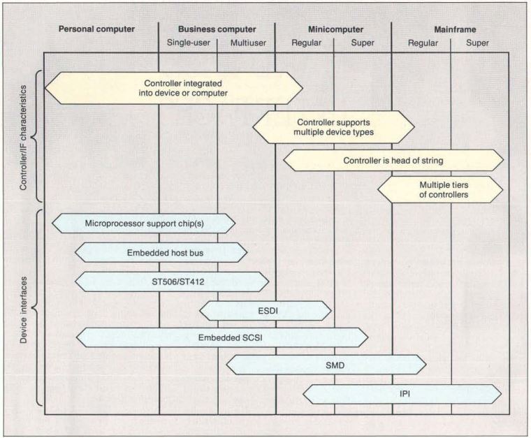
Figure 1: The solution regarding which hard disk drive interface is best suited to your computer depends on your machine's complexity and performance.
ST506: The First Standard
The use of hard disk drives on microcomputers is a relatively recent phenomenon. While they were available for many early machines (S-100 systems and even the Apple II), the boom did not begin until 5 1/4-inch hard disk drives first appeared in the early 1980s. Shugart Technology (now Seagate Technology) pioneered the manufacture of these' small-form-factor disk drives with the 5-megabyte ST506 hard disk drive.
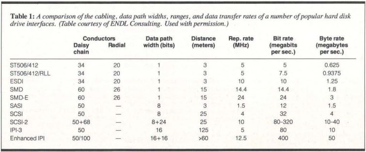
Table 1: A comparison of the cabling, data path widths, ranges, and data transfer rates of a number of popular hard disk drive interfaces.
The ST506 was derived from two other interfaces: the SA450 interface for 5 1/4 -inch floppy disk drives and the SA1000 interface for 8-inch hard disk drives. Like the SA450, the ST506 used a 34-pin daisy-chain cable for control signals; like the SA1000, it used individual 20-pin "radial" cables to carry data between the controller and each disk drive (see table 1). It's no coincidence that this feature also allowed cables from existing disk drives to be used on newer ones.
The ST506 interface was designed to read and write data at a maximum rate of 5 megabits per second- not as fast as a disk drive using SMD (the mainframe standard of the day), but still faster than the microcomputers available at that time could accept.
A problem with the original ST506 interface was that, as with a floppy disk drive, the read/write head had to be stepped (moved across the disk) one track at a time by carefully timed pulses. Since these pulses actually caused the read/write head's stepper motor to advance a notch, they could not proceed faster than the disk drive could move the head.
The ST412 disk drive introduced an enhancement that eliminated this problem: the buffered seek. Instead of requiring the controller to slow the pulse rate to whatever the mechanism could handle, the ST412 simply counted the pulses as they came in. It then decided for itself how fast to step the head to move the required number of tracks.
Enter RLL Encoding
While the ST506 standard was sufficient for many applications, disk drives were still expensive. Thus, manufacturers sought ways to pack more data onto a single ST506 disk. Many companies began to use a compression technique invented by IBM called RLL encoding, which squeezed 50 percent more space and speed out of an ST506 disk drive. To use RLL, you need a controller that's specially designed to use this encoding scheme (see the text box "RLL Encoding").
//----------------------//
RLL Encoding
The encoding scheme called run length limited (RLL) is useful for squeezing the largest possible amount of data onto a hard disk drive. To understand how encoding schemes work, let's look at the three most common ones used today: frequency modulation (FM), used on older floppy disk drives, modified frequency modulation (MFM), used on current floppy disk drives and many hard disk drives, and 2,7 RLL (used on most RLL hard disk drives).
Data on a magnetic disk is recorded as a series of pulses and silences. In the FM encoding scheme, each 1 or 0 is represented by a pattern consisting of pulses and silences. For example, a silence followed by a pulse is a 0, and a silence followed by two pulses is a 1. The pulse that's always there is called the clock pulse. Because there is a clock pulse in every bit, it's easy for the controller to keep pace with the data as it comes in (a process known as clock extraction).
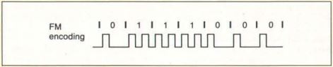
Figure A: In FM encoding, each bit is represented either by a pulse and a silence (0) or by two consecutive pulses (1).
Figure A shows why this technique is called FM. Twice as many pulses occur per unit of time during a string of 1s than during a string of 0s, and the average (for an even mix of 1s and 0s) is 1.5 pulses per bit.
The constraint that determines how much data you can get on a disk is simple: There must be enough space between pulses so that they don't run together. FM encoding always leaves room for two pulses per bit, in case that bit is a 1. The maximum number of bits you can have, therefore, is always half the maximum number of pulses you can fit in. There is, however, a way to use fewer pulses to represent the same data. This is the idea behind MFM (see figure B).
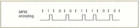
Figure B: In the MFM encoding scheme, all pulses are separated by at least one silence. Since the amount of data that can fit on a disk depends on the closeness of successive pulses, MFM allows twice the data density of FM encoding.
In MFM, the encoding rule is as follows: A 1 is represented by a silence followed by a pulse; while a 0 is represented by one of two patterns: a pulse followed by a silence if no pulse occurred at the end of the previous bit, or by two silences if a pulse did occur at the end of the previous bit.
The MFM scheme guarantees that there will always be at least one silence between pulses (so that they can be packed more tightly without running together), but no more than three (so that a clock can still be recovered). This pattern yields an average of 0.75 pulse per bit (assuming that 50 percent of the 0s are represented by each of the two possible patterns), and it therefore lets you pack the bits twice as closely together. For this reason, when MFM floppy disks first came out, they were called double-density disks.
ST506 hard disk drives originally used MFM encoding. Is there another encoding scheme that could increase the density still further? To answer this question, let's review the schemes just discussed in terms of run lengths, the minimum and maximum numbers of consecutive silences in each encoding scheme.
FM allows a minimum run length of o (it's possible to have no silences between pulses) and a maximum run length of 1 (there's always a clock pulse after a silence). So, one way to describe FM is as 0,1 run-length-limited encoding, or 0, 1 RLL for short. Similarly, MFM always has at least one silence between the pulses, but no more than three-making it 1,3 RLL. It's the minimum run length that determines how tightly data can be packed onto the disk, while the maximum run length determines how accurate the controller must be at timing when the pulses come in (so that it can generate a clock to go with the data).
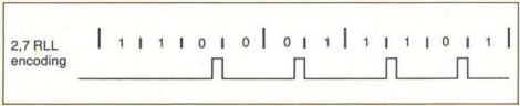
Figure C: Here's how a sample bit pattern is encoded in the 2,7 RLL scheme. Each code group is 4 to 8 half-bits long and is encoded from a code group of 2 to 4 data bits. The length of the pattern corresponds to the length of the original data, but the pulses are guaranteed to maintain the required minimum and maximum spacings.
The encoding scheme we know simply as RLL is usually 2,7 RLL (see figure C and table A). It uses a more complex set of rules to determine the pulse pattern for each bit based on the values of the preceding bits, but the principle is the same: There are fewer pulses, but their precise positions convey more information about the original data pattern.
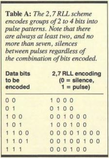
Table A: The 2,7 RLL scheme encodes groups of2 to 4 bits into pulse patterns. Note that there are always at least two, and no more than seven, silences between pulses regardless of the combination of bits encoded.
//--------------------------------//
At first, using RLL encoding on an ST506-type disk drive was a risky proposition. RLL requires higher precision in the recording circuitry, medium, and disk drive mechanism than the usual modified-frequency-modulation (MFM) encoding technique. Thus, for RLL, disk drive manufacturers had to add tests that certified correct operation. Today, however, virtually all manufacturers offer RLL-certified disk drives that meet the higher tolerances.
A typical ST506/RLL disk drive will provide a net data transfer rate of 7.5 megabits per second, and because it can fit more data on a track than a non-RLL disk drive, it will probably need to step the heads less often as well.
Advanced and Enhanced RLL
The initial RLL schemes had the advantage of expanding disk drive capacity while keeping the repetition rate- the maximum frequency of the pulses present on the data cable- at or below the rated 5 MHz. Some controller manufacturers, however, attempted to increase the repetition rate as well, to 6.7 MHz. These schemes- ARLL (advanced RLL) and ERLL (enhanced RLL)- resulted in a 100 percent increase in space and data transfer rates over the original ST506 designs.
ARLL and ERLL systems experience more problems than RLL systems; however, because they push the disk drives far beyond their original design limits. At these speeds, the disk drives became very sensitive to temperature variations, slight differences in manufacturing tolerances, and cable lengths. Few manufacturers wanted to take the time to certify that their disk drives would work under these conditions.
For these reasons, you may want to think twice before buying an ARLL or ERLL controller. If you want additional speed, consider an ESDI or SCSI disk drive instead.
ESDI
As early as 1983, manufacturers of disk drives and controllers saw a need for a standardized, reliable interface with a greater throughput rate than the ST506. To this end, Maxtor, a hard disk drive manufacturer, initiated the development of the ESDI standard.
While the cables for ESDI are exactly the same size and shape as those for the ST506, ESDI provides a number of new features that greatly enhance performance. It also has provisions for support of optical disks.
What's different about ESDI? Well, the most important change was the move of the data separator (a component that extracts data and clock pulses from the signals received by the head) from the disk drive controller onto the disk drive itself. This change had two main benefits: The signal was not as likely to be degraded in long runs of cable, and the data separator itself could be "tuned" to the characteristics of the disk drive and medium. Because ESDI does not use any analog signals on either cable, it can easily achieve data transfer rates of 10 megabits per second, and it has a theoretical capacity of 24 megabits per second or more.
In ESDI, control signals also are streamlined. While the head can still be stepped a track at a time (as in the ST506), an ESDI controller can also specify the desired track using a binary number. Other ESDI commands can ask for configuration information-for example, whether the drive is a WORM (write once, read many), status (such as whether a removable medium has been changed), or diagnostic tests.
SMD
Control Data Corp. (CDC) developed the SMD interface for large fixed and removable disk drives., Until the introduction of the IPI standard, SMD was the standard interface for disk drives with large capacities and diameters larger than 5 1/4 inches.
Like ESDI, SMD has a data separator on the controller that permits a data transfer rate of 14.4 megabits per second. A data transfer rate of 24 megabits per second is available on an SMD-E, an enhanced version of SMD. However, because other standards are easier and less expensive to implement, SMD disk drives are not often used on microcomputers. When you do see one on a microcomputer, it is generally in a file server that uses very large disks, like the Fujitsu Eagle.
SCSI
SCSI was developed in the late 1970s as an interface between a computer and an intelligent disk drive controller. Introduced by Shugart Associates as SASI (Shugart Associates system interface), it allowed computers to issue commands and receive data over a simple parallel bus with a byte-wide data path and a relatively small number of control signals.
This scheme had many advantages for computer manufacturers. Rather than having to design controllers for the ST506, SMD, or other disk drive interfaces, the companies could provide one interface-SCSI-and let the user or a systems integrator attach an intelligent controller and a matching disk drive. In theory, a computer that uses a SCSI interface to communicate with its disk drives needs to know little about their physical or electrical characteristics, and it can often find out what it needs to know by querying the disk drives themselves over the SCSI bus.
This device independence has proved attractive to manufacturers of other kinds of peripherals. You'll see SCSI interfaces on tape drives, floppy disk drives, Bernoulli boxes, portable RAM disks, and even Ethernet controllers. (At least some of the more esoteric SCSI peripherals were developed because Apple's Macintosh Plus and SE computers have little or no internal expansion capability but do have a SCSI port on the back.) Most disk drive manufacturers now offer products with embedded SCSI controllers, eliminating the need for a controller board between the SCSI bus and the disk drive.
SCSI has evolved and changed greatly over the years. The original SASI interface transferred data at a maximum rate of 1.5 megabytes per second; enhancements in SCSI allowed synchronous transfers at up to 4 megabytes per second. The SCSI-2 specification, which has already been adopted by many manufacturers and is soon to be an ANSI standard, will allow transfers at up to 10 megabytes per second, and it provides for an optional 16-bit or 32-bit data path for even faster transfers. It also contains provisions for caching disk drive controllers, printers, communications controllers, CD-ROMs, WORMs, and erasable optical disks.
Using all the capabilities of SCSI-2, it's theoretically possible to transfer data at a blazing speed of 40 megabytes per second-far faster than most microcomputers now available could accept it. Real-life implementations, however, will probably not provide this capability for quite some time.
A thorough description of SCSI could (and, in fact, does) fill several thick volumes. The important thing to note about SCSI is that it supports a far wider variety of devices than any of the interfaces I've mentioned previously-without necessarily imposing a penalty in speed. Given the right hardware and software, a SCSI interface can support not only your disk drives, but also a large number of other peripherals that would otherwise require separate controller cards.
There are some incompatibilities in the command structures used by different machines to talk to different devices, but industry specialists are even now working on a new standard called common access method (CAM) to eliminate these problems. All in all, the future of SCSI looks bright. Perhaps this is why Sun, Apple, and NeXT (among others) have opted to use SCSI as their exclusive interface to hard disk drives.
Intelligent Peripheral Interface
IPI is a standard designed for high-end systems like mainframes from IBM, CDC, and Unisys. Among the features it supports are long cable lengths (up to 125 meters), large numbers of disk drives, and very high data transfer rates (80 megabits per second and above). IPI uses multiple controllers that can be highly intelligent and can hide physical device characteristics.
You're not likely to see IPI on microcomputers in the near future-or maybe ever. But due to its higher speed, it will probably supplant SMD as a standard for large storage devices in the mainframe world.
Choosing an Interface
What does all this mean to you as a user? The vintage ST506 interface, available on the largest number of hard disk drives sold today, can be a bargain. This is especially true if you have a computer like the IBM PC AT, which comes equipped with a controller for these drives. If you currently have an ST506-type controller on your machine, you may wish to move to an RLL controller to squeeze the last bit of storage out of your drive. This is recommended, however, only if your drive is RLL-certified. (If you buy both a drive and a controller from a competent dealer, the dealer should sell you only an RLL drive with an RLL controller.)
If you're buying a new machine or upgrading one without a hard disk drive, you should consider ESDI or SCSI-especially if you want top performance. If SCSI is available, you will acquire the possibility of connecting to tape drives and other devices. SMD may be a useful solution if you need to hook up to an existing disk drive with that same interface, but SMD probably is not a good solution if you're going to buy new disk drives.
Ultimately , the performance you get from your disk drive will depend on more than just the interface. Features that may have a far more dramatic effect than the interface alone include the quality of your software, the interleave factor on your disk drive, and the presence or absence of caching. Be sure to take all these factors into account when selecting your hard disk drive system.
Special thanks to I. Dal Allen of ENDL Consulting for his help in preparing this article. Also, thanks to Steve Gibson of Gibson Research, who first successfully explained to me how RLL encoding worked.
Brett Glass is a freelance programmer, author, and hardware designer residing in Palo Alto, California. He can be reached on BIX as "glass. "
GLOSSARY
ARLL Advanced-Run-Length-Limited encoding; a variant of RLL in which additional speedup techniques are used to squeeze more data onto the disk.
Buffered Seek A feature that allows a disk drive to accept step pulses-signals that cause the head to move across the disk faster than the head is able to move. The pulses are remembered (buffered), and the head is moved to the desired location as fast as possible.
CAM Common Access Method; an evolving standard that will let programmers on different computers use the same source code to control SCSI devices.
Data Separator This device extracts and decodes data and clocking information from the raw signals received by the read/write head of a disk drive.
ERLL Enhanced-Run-Length-Limited encoding. See ARLL.
ESDI Enhanced Small Device Interface. This serial device-level interface, designed for disk drives only, improves on the ST506 interface by performing data separation on the drive and allowing the controller to send the drive binary commands over a parallel bus.
FM Frequency Modulation. The simplest but least efficient way of encoding disk data, it's virtually never used on hard disk drives. It's called frequency modulation because the pulse rate varies depending on whether the current bit is a 0 or a 1.
IPI Intelligent Peripheral Interface; a mainframe standard that allows long cable lengths, distributed control, and high data throughput.
MFM Modified Frequency Modulation. This encoding technique, also called double-density when used on floppy disks, allows twice as much data per track as FM.
Repetition Rate The maximum frequency at which the data lines of an interface can transmit data bits. Multiplying the repetition rate by the width of the data path yields the data transfer rate of the interface.
RLL Run-Length-Limited encoding. An extension of MFM, RLL uses a complex scheme to separate pulses still further on the disk and allow for still higher data densities. Most systems described as RLL use 2,7 RLL encoding; a few use 1,7 RLL. (See the text box "RLL Encoding" on page 296.)
SCSI Small Computer System Interface. This parallel bus standard is designed to interface small computers to disks, tape drives, and other peripherals. It requires' intelligence in each
peripheral.
SMD Storage Module Device interface; a venerable mainframe standard that is slowly falling into disuse because of its cost and the emergence of faster interfaces.
STS06 The hard disk drive interface introduced by Seagate in its ST506 5 1/4 - inch hard disk drive. This interface has become a de-facto industry standard.
Step The process of positioning the disk drive head to the chosen location on the disk by moving it incrementally in the desired direction, one notch at a time.