6094 Lighted Program
Function Keyboard Model 020
189-166 IBM ... 6094 Lighted Program Function Keyboard Model 020 [P/N 39F8226]
Japanese IBM MICRO CADAM LPFK P/N 79F1028
IBM LPFK on a Serial Port
liblpfk -- IBM LPFK driver library
Scoop on IBM Dials and Buttons boxes?
CADAM Function Key Box [external power supply]
The Model 90 was supposed to be a CAD station, and the 1MB XGA with 1,024x768 @256 colors, was touted as a worthy video adapter for CAD of that day. I've been OK with letting rumors be rumors, until Tatsuo Sunagawa dredged up a brochure for the 5560-N
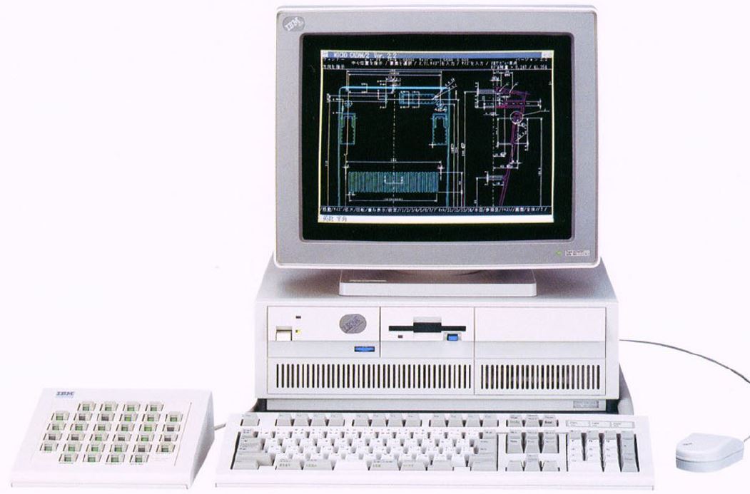
If you click on the image to view the two page brochure, you will see "MICRO CADAM/2 ver 2.2" at the upper left corner of the screen.
These P/N may have been correct at one time...
Attach 6094-020 to PS/2
Attachment Cable
39F8228 / 6247461 [PC-PS/2 Attach (9)] ; connect LPFK to Serial port
39F8229 / 6247460 [PC-PS/2 Attach (25)] ; connect LPFK to Dual Async Adapter ???
NOTE: Dual Async has two DB9 ports.
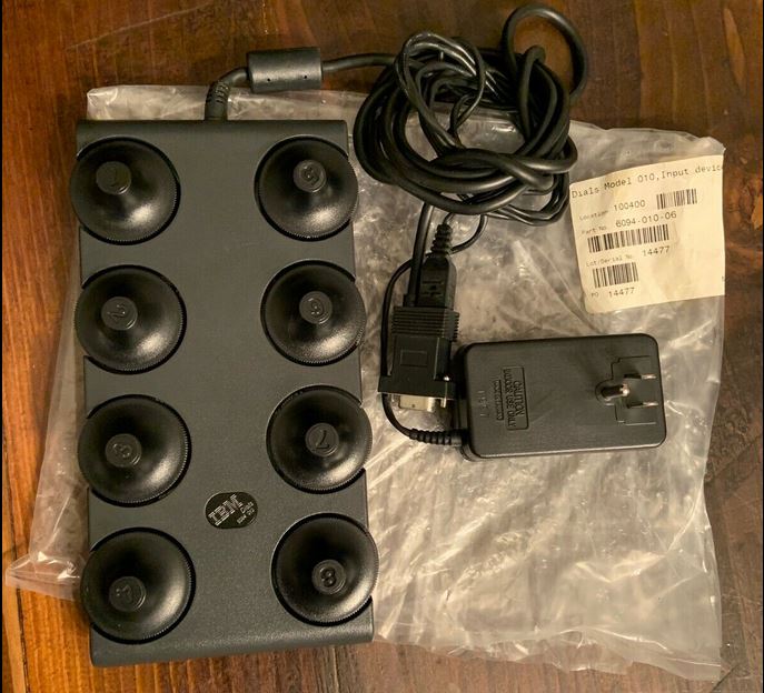
Notice that there is a moulded plug from the AC adapter that plugs into the back of the DB9 adapter... When the serial port to Mini DIN8 is figured out, you could use a DB9 breakout box, then just drill it for a DC barrel jack...
5v 500mA power supplies
6247468 Power Supply; 120 V for attaching LPFK to any PS/2.
6247469 Power Supply; 220/240 V for attaching LPFK to any PS/2.
6247470 Power Supply; 220/240 V for attaching LPFK to any PS/2 in the UK.
Diagnostics Diskette
39F8224 Diagnostic Diskette; 3.5-inch for attaching LPFK to the PS/2.
32-key Alps SCKL Yellow-based keypad [SKCLFM Green LED fitted ?]
Tatsuo remembers:
SKCLFM is Single Key switch, Yellow stem, Linear action, with a green LED installed.
Basically, main switches are brown color stem, tactile. Tactile (and Clicky) switches are coded as SKCMxx. But there is no room for a LED in the SKCM. LED can be co- existed only with Linear action switch.
FYI, old version came with a Green stem.
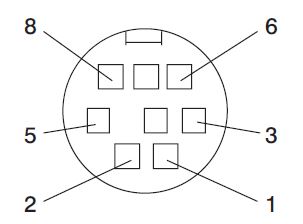
8-position mini-DIN connector
NOTE: Treat this as unconfirmed. You have been warned.
Graphics Input Adapter MCA card (Type 6-1, FRU 22F9758)
1 Signal Return
2 DC return
3 +5Vdc
4 Selective reset to device
5 RX data from device
6 TX data to device
7 Diagnostic selective reset from device
8 Reserved
10 Pin MODU Pinout
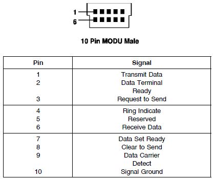
My guess... The RS6000 pinout used common RS-232 lines. So we need to compare the Graphics Input Device Adapter (Type 6-1) port to the 10 pin MODU port... If we had a MODU to Mini DIN8 cable...
#4060 39F8228 LPFK, Dials or Tablets Serial Cable (6ft) Cable-HH
#4061 39F8302 LPFK, Dials or Tablets Power Cable (6ft) Cable-JJ
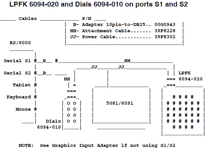
LPFK 6094-020 and Dials 6094-010 on ports S1 and S2
Cable-B Adapter Modu-to-DB25 S1/S2
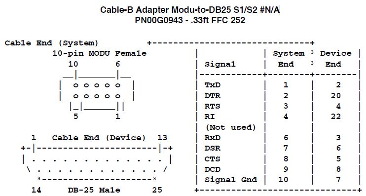
And this gets us nowhere. We need the "HH" cable pinout.