|
8642 PC Server 720
Dennis, please quit bothering me!
84h7085.exe
PC Server 720 reference diskette version 1.12
720pci.exe
720PCI PC Server 720 PCI Configuration Diskette
4227103.exe
PC Server 720 diagnostic diskette version 1.13
4305348.exe
PC Server 720 BIOS flash update level 14 ver 1.10
4305348a.txt
README file for BIOS flash update level 14 ver 1.10
BIOS 10 and diags 1.12 and later properly reset memory cache after testing.
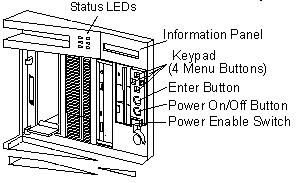
Front Panel

Status LEDs and Information Panel

Status LEDs
Green = proper operation Yellow = alert condition
|
LED#
|
Definition
|
|
1
|
Hard disk drive activity
|
|
2
|
DASD error
|
|
3
|
Processor Complex Error
|
|
4
|
Color green (POWER GOOD)
|
|
5
|
Color green (POWER Enabled)
|
|
6
|
Color green (All subsystems good)
|
Error Codes
Corollary Errors (CP,TP,EP,IP,FP,HALT)
PCI Errors (DDDD DD S
0 VVVV IIII)
General Errors
Liquid Crystal Display
The Liquid Crystal Display (LCD) on the front operator panel
contains a 2-line by 16-character LCD (front panel display) driven by the
80C752 microprocessor. The front panel display receives and transmits ASCII
characters. The LCD supports the upper-and lower-case ASCII character set.
Errors detected by the computer might be displayed on
the LCD and/or on the standard display attached to the computer. This is
helpful when a display is not attached to the computer or the attached
display is inoperative.
LEDs - System Board and Adapter
LED(s) are located on planar, bridge, processor, and memory
card.
| Component |
LED On |
LED Off |
| Planar Slot LEDs: B1 (bridge card
slot) |
During / after normal initialization of bridge card |
-SW problem preventing initialization of card
-Defective LED
-Defective bridge card |
M1
(memory card slot) |
During initialization of memory card |
Successful initialization of memory card complete |
M2/P1
(w/ memory card installed) |
During initialization of memory card |
Successful initialization of memory card complete |
M2/P1
(w/ processor card installed) |
During initialization and activity on processor card |
- No activity on processor
- SW problem preventing initialization of card
- Defective LED
- Defective processor card |
P2 thru P6
(with processor card installed) |
During initialization and activity on processor card |
-No activity on processor
- SW problem preventing initialization of card
- Defective LED
- Defective processor card |
| Micro Channel slots |
When computer is powered-off |
When computer is powered-on |
| Bridge card LED |
During / after normal initialization of bridge card |
- SW problem preventing initialization of card
- Defective LED
- Defective bridge card |
| Memory card LED(s) |
During initialization of memory card |
Successful initialization of memory card complete |
| Processor card LED(s) |
During initialization and activity on processor card |
-No activity on processor -SW problem preventing initialization of
card
-Defective LED
-Defective processor card |
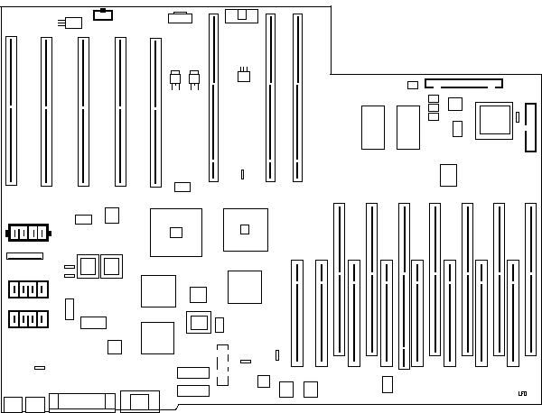
PC Server 720 Planar

I²C (Inter-Integrated Circuit)
The I²C (Inter-Integrated Circuit) bus is a serial
bus that is used in the PC Server 720 to monitor and control several peripheral
functions within the machine. The bus is driven through a VLSI module on
the system board. A service processor on the system board (based on the
Intel 83C552 micro-controller) controls and monitors these functions within
the machine through the I¥C bus. These include:
The front panel LCD
The front panel power controls
Detecting the setting of the SCSI ID
jumper on the hot-swap backplanes
Reading the voltage and temperature
sensors on the planar (these can be viewed by the operator using NetFinity)
Controlling the three fans mounted behind
the drive bays
9595 Main Page
|


