|
7568 System Resource Card
@8EF7.adf
System Resource
System Resource Card
System Resource Card Status Lights
RUN/CHECK
SPEAKER
Hexadecimal Display.
Three Port Cable Assembly
Data Ouput Points
DO1
Catastrophic Check
DO2
Non-Catastrophic Check
DO3
Speaker Interface
Setup and Service
Device (Units without FDs or HDs need this)
Keyswitch
Keyswitch Connection
Combinations
8EF7 ADF Sections
System
Resource Card FRU 15F8577
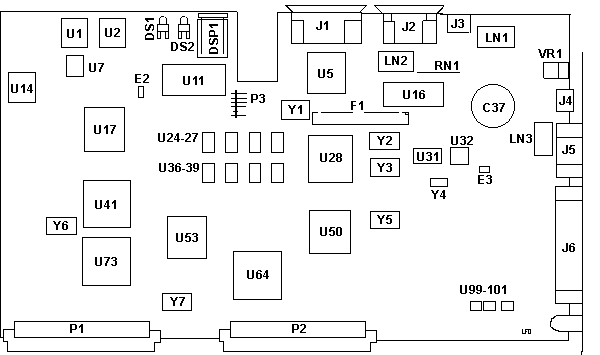
C37 RTC backup (5v 1F cap)
DS1 Run/Check LED
DS2 Speaker LED
DSP1 2 digit display
E2 Speaker
header???
E3 Password
erase
P4 Floppy
conn
J1 Setup
and Service Device Port
J2 Video port
J3 KB/Mouse port
J4 KB/Mouse port
J5 Bottom video port
J6 Breakout
Cable port
LN1 Unk
LN2 Unk
LN3 Unk
P1,2 Backplane connectors
P3 Keyswitch connector
RN1 ?
U1,2 82C55A-2
U5 82077AA floppy ctrl |
U7 82C54-2
U11 RPL socket???
U14 57F0838
U16 Inmos IMSG171P-35
U17 33F5953
U24-27,36-39 Video mem (4146?)
U28 92F0616
U31 SRM2264LM12
U32 MC146818AFN RTC
U41 90X8134ESD
U50 33F5469
U53 Xilinx XC3020-70
U64,73 57X41111
U99-101 GE H1162
Y1 24.0 MHz
Y2 28.322 MHz
Y3 25.17500 MHz
Y4 32.768 kHz
Y5 22.11840 MHz
Y6 20.0000 MHz
Y7 14.31818 MHz |
Tony I sez:
Double connector sets for Video, KBD, FDD. One on
bottom, one in front. Large connector on bottom for built in digital I/O
signals
Ed. Only one monitor can be attached
to the video ports at a time!
Support for the PS/2 XGA Display Adapter/A requires that the System
Resource Card Graphics Support Upgrade (#6886) be installed on earlier
models of the GEARBOX Model 800.
Erase Power On Password
System Resource
Card Status Lights
RUN/CHECK
Green means SRC is OK
Red means system detects
an error on the SRC
Off during system reset. BUT if it remains off after
system reset is complete, an error may have occured between the SRC and
other cards in the unit.
SPEAKER
Amber light is off during normal operation. It is lit
whenever a program activates a speaker. E2?
Hexadecimal
Display.
00 is the usual running display.
Three Port
Cable Assembly (System Resource Breakout Cable)
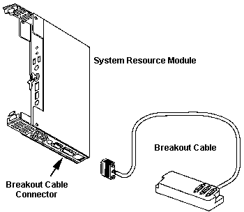
Connection from System Resource Card in the system to various
other standard connectors Serial (RS-232/422), parallel, and System Digital
Output (DO) devices.
The 3' breakout cable attaches to the 78 pin D shell connector
on the bottom of the system resource card. There are three D shell connectors
on the breakout box (similar to the Multiport box).
Data Ouput
Points
A 15 pin D-Sub on the breakout cable has three optically
isolated Data Output Points:
DO1 Catastrophic
Check
Cannot be controlled or reset through OS. Indicates one
or more of the following:
--Watchdog timer has tripped and the processor
is no longer functioning normally.
--ECC on the processor has found a fatal memory
error. The system may not continue to run.
--I/O channel Check caused by
ECC check on an adapter
Parity check on the bus
I/O channel check by an adapter
--Temperature check
Processing can continue but damage to the system
unit may occur.
Activated when exhaust air of the power supply >60
degrees C (140 degrees F).
--Other catastrophic errors noted by SVAL.
WARNING: If temperature check is ignored
and internal PSU reaches damaging levels, the system will shut down without
warning.
DO2
Non-Catastrophic Check
Controlled by operating system. Examples: 'fan failed",
"battery is low", or "battery missing".
DO3 Speaker
Interface
Speaker connection controlled by OS and system BIOS/SVAL.
Setup
and Service Device (#6230):
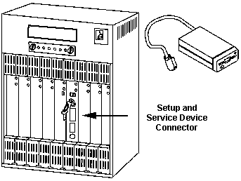
A stand-alone 1.44MB, 3.5" diskette drive in an enclosure, used for
initial system set-up, loading diags and recording test results on a Gearbox
without a DASD module. It plugs into a DB26 port on the System Resource
Card. This port must have the power and signal leads in it.
Keyswitch
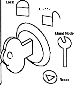
C&K Components, Inc. Y100AB2C801NQE
4 Tumbler, single pole. Termination - Solder lug w/notch, seal - Epoxy
LOCK SVAI runs, system starts
normally. KB is locked.
UNLOCK SVAI runs, KB can be used
MAINT MODE When powered off, system
bypasses battery backup function. Use only during diagnostic proceedures.
RESET Turn to Reset then back to
any other position.
Keyswitch
Connection Combinations
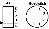 Lock
8,1,3 Lock
8,1,3
Unlock 8,3
Maint 8,2,3
Reset 8,3,4
AdapterID 8EF7 "System
Resource"
Diskette Primary/Alternate Address
Selects primary or secondary address for diskette adapter
on the SRC. This floppy controller is disabled if a DASD Module is installed.
<"Alternate 0370-377"
>, "Primary 03F0-03F7"
BIOS Ext. ROM Segment xxxx-xxxxx
Enables for address ranges of the optional BIOS Extension ROM
on the System Resource Card. Each enable covers a specific address
range. More than one enable can be active to allow larger address.
BIOS Ext. ROM Segment 0D0000H - 0D1FFFH
<"Disable">, "Enable "
BIOS Ext. ROM Segment 0D2000-0D3FFF
<"Disable">, "Enable "
BIOS Ext. ROM Segment 0D4000-0D5FFF
<"Disable">, "Enable "
BIOS Ext. ROM Segment 0D6000-0D7FFF
<"Disable">, "Enable "
BIOS Ext. ROM Segment 0D8000-0DBFFF
<"Disable">, "Enable "
BIOS Ext. ROM Segment 0DC000-0DFFFF
<"Disable">, "Enable "
9595 Main
Page
|

