Ultimedia Model 77 Front Panel / PCB
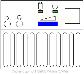
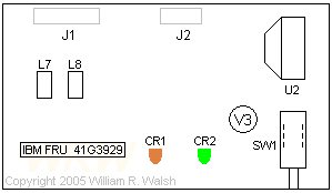
For those not fortunate enough to own a Model 77 Ultimedia, here is what the front panel and PCB would look like, along with some other information. I would assume the Model 57 Ultimedia panel is similar as circuit boards go.

I would assume that the "circle with a flat side" symbol above is IBM's way of saying "plug your microphone in here". I haven't actually tried that yet. The speaker behind the grille is a much larger unit than is present in the normal, non-Ultimedia front panel. It is rated 1.5 watts and 8 ohms as compared to 0.5 watts at 4 or 8 ohms. The shape is an oval cone set into a square frame. Both the headphone and microphone plugs are 1/4 inch type.
The blue mark is a volume control wheel. Sound quality and volume from this unit are actually pretty good considering the size and housing.

CR1 - Hard disk activity LED
CR2 - Power LED
U2 - Philips TDA1015 1-4 watt self contained power amplifier (datasheet)
L7, L8 - TDK ZJYS-4
V3 - PCB Printing
SW1 - Power switch
J1 - "Ultimedia Header" to sound card
J2 - "Power Header" to planar/system board
I would assume that the connection to the sound card powers the onboard amplifier. With the sound card cable unplugged the volume control ceases to function and the speaker plays all beeps as a normal front panel would.
Go Back>
Copyright © 2005 by William R. Walsh. All Rights Reserved. This page may be reproduced freely in its original form with all copyright noticies present and unaltered as long as no charge is assessed for providing this information, other than reasonable charges for duplicating, media cost, or connection/access time.

