|
Hey Buddy - what's that now again !?
In brief: a sort of variation from the Cookiebox, to achive a simple, small monoblock amplifier.
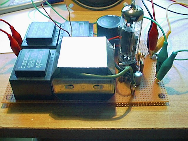
And that started with digging through my boxes of unsorted stuff, where I found another box, which contained a dozen of small printboard transformers. They are made by Gerth, type BV 4212-1. Each capable of doing 4.5 VA, 230 V input, 1 x 12 V / 400 mA output and only 37 x 45 x 33 mm small. I'd looked at them and thought, what might come out if I operate two of them "back-to-back" for an anode supply, use one as a heater transformer for a single PCL86 and mis-use a fourth one as output transformer.
Well - but power transformers aren't the best output transformers anyway. And that's because they lack an air-gap that prevents the immediate saturation of the transformer core by the anode current.
"To the heck ...!" I'd thought. "We're just testing it out."'
Been there - did that.
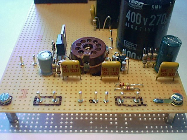
Four transformers, one nine-pin socket, some smaller components - that nicely fits onto a "Europe" experimental board of 100 x 160 mm size. The basic amplifier layout has been taken from the "Cookiebox" design. It was quite clear that I'd end up with a rather low anode voltage supply and that it cannot be loaded very high.
A simple calculation example with the transformer data leads to 230 V / 12 V = 19.17 transformer ratio. 400 mA / 19.17 = 20.86 mA in the best case, if I connect two identical transformers with their secondaries. That does not take in account, that I have conversion losses and that the voltage drops under load. But it should do as an estimation.
Given I'd use 20 mA for a start, the output pentodes should come out at the half of it as idle anode current. That would be around 10 - 11 mA. That's pretty low for a PCL86; just at the lower bottom of the useable characteristics.
Now let's have a look on how suitable these transformers are when being used as output transformers. They have about 800 Ohm DC-resistance on the primary and about 5 Ohm on the secondary. Let's have a calculation on the primary impedance: at 230 V input they should deliver 12 V output. That the ratio of 19.17 mentioned further above and what we need to know. Any output transformer would have been tied with the primary to mains-AC and then checked for its secondary output.
But careful - Mains-AC is lethal !
You'd better use a separation transformer or any lower level AC. I - for one - use to take the 24 VAC from the supply unit of my ERSA ELS 8000 solder station - that works fine as well with lesser danger.
Using mains-AC has only one advantage: if the fuse blows the transformer can be disposed. Either its isolation is damaged or its inductivity is too low.
Whatever: input voltage divided by output voltage results into the transformer ratio. If you attach a 4-Ohm-speaker you simply calculate a square of the ratio and multiply it with 4 Ohms. That results in about 1470 Ohm primary impedance. Pretty low, eh ? Basically that alone would have been a Knock-Out criteria, but "It is just an experiment" - we try it out nontheless.
I'd figured, that we might come out with around 5 - 7 V at a cathode resistor, so I designed the cathode current regulator to about 3 Volt. Of course the S.o.C. inherited that thing from Cookiebox. The design is easy done with standard resistors: 100 Ohms for the 'upper' R1 and 150 Ohms for the 'lower' R2.
After the known calculation 1.25 x (1 + (R2 / R1)) the output should settle at around 3.125 V. These 3.125 V divided by the values for R1 + R2, which act as setup and sole load, result in 12.5 mA current flowing through the regulator and therefore through the cathode circuit on the pentode.
Hmmm. Wonder if that turns out fine.
Of course it didn't.
The transformer was capable to produce some music, but the distortions reached unbearable measures even at low output levels. So something else must be found. Further digging in my stuff turned up with a pair of nice Grundig OPT's that might fit in electrically and which could - given some creativity and ingenosity - be adapted to fit in physically for that purpose.
Originally intended purpose was a final amplifier with a single EL95. The OPT's have around 680 Ohms DC resistance and a transforming ratio of about 50. Which then results in a primary impedance of 10K when loaded with a 4-Ohm speaker. That looks far better already from the theory.
Along with the Grundig OPT's and set up to about 12.5 mA cathode current the little beasty sounds pretty nice at lower output levels. Subsonic base are not achieveable of course. The anode voltage is gained from the raw AC with a quad of 1N4007 diodes, which are soothed by a single 270�F / 400 V capacitor. Parallel to that resides the well-known 100 nF / 500 V ceramic capacitor to filter out high-frequency spikes. Other people use Polypropylene caps here - but that does not matter much anyway and since I still have a bag full of them I used these of course. In idle without a tube the voltage peaks at about 250 V and drops down with the tube installed to about 170 V, as soon as the tube heater comes up and tube comes conductive. The voltage at the anode is then about 166 V, that on the triode part is around 94 V, which is not too bad.
During experimenting I'd made the mistake to run the circuit without a resistor across the input. Wow ! Flying sparks, where GND and supply HV are closer to each others. A minor noise across the input is enough to let the "weak" power supply and the "strong" pentode oscillate. That again pushes the voltage into enormous heights until it finds a discharge elsewhere on the printboard. Not so good. So I'd installed a 4K7 resistor across the input. That will do to reach a gain level where testing with a headphone output from a computer soundcard is possible. That's fine so far. For using the circuit with e.g. a CD player line out the resistor might be substituted with a 47K.
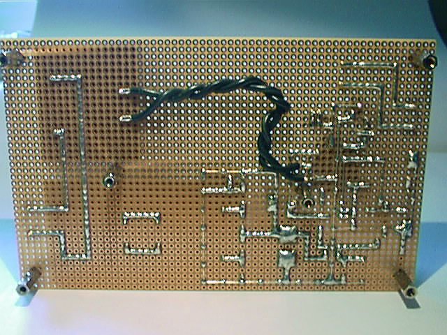
The tube is only heated with 12 VAC from the third transformer. Two thick, short and twisted wires at the underside of the circuit board fed the heater voltage onto the tube socket. Pin 4 of the PCL86 is then directly tied to GND. Surprisingly there is no audible hum. Faint "thermo-ionic noise" in the speaker is all of the noises from that unit.
Since a single amplifier does not suffice for Stereo I'd built an identical twin "just so" during one evening, after my favourite supplier Reichelt delivered the required resistors and Euro-Printboards. Without a printboard it is difficult to built up an amplifier. Not impossible - but unneccessarily difficult. On the other hand ... if you think closer it might be possible to make a boardless design ... but that's a different story again. Maybe later.
Next to come are cases.
I don't want to make unneccessary fuss with these - a U shape from sheetmetal, with the sides high enough to fit in Mains-AC input socket (with integrated fuse), double pole power switch, speaker terminals, RCA chinch input jacks and volume control. Probably a LED that signals the status - but that's not needed. Then - acting as cover and protection - another U-shaped metal grid over the whole thing.
But my intentions and motivations for building cases generally lag far behind my electronic activities. In most cases my gear ends up with no case or had been installed into "something else". That was originally the reason for the "Cookiebox" name, since it should have been installed in an old cookie box (and never had been installed there ... so far !)
Testing Results and more Considerations
Of course I tested the S.o.C. "Mono-Blocklets" troughout in the meantime. While the "Cookiebox" had been taken away for further minor modifications, I'd took the occasion to install and test the two units on that place on the workbench.
The surrounding environment is still the same: IBM PC300GL (6561-350) with Creative Labs Soundblaster 1024Life! as sound source. To be fed from WinAmp 2.93 wth MP3-sounds, resp. a CD / DVD Multiformat-Burner with the digital output tied to afore-mentioned soundcard gets music from off these silver, round disks. The speakers are my good old and welknown arcus sinus two-way speakers. Closed, 4 Ohm, 40 / 60 Watt.
Evan though these speakers are not just the most high efficient types the two amplifiers produce a fairly good result with them. They lack - of course - the push from the bottom, the achieveable volume is far from being impressive and the audible distortions start at mediocre sound levels already. But they are more than sufficient for a nice musical background during work. Occasionally the volume level can be a tad higher, but the musical material shouldn't be Techno, Rave, Punk or blown-up basses from studiowork. Everything with a balanced frequency comes out quite nice.
Voices are brought out fine, percussion is well-defined, strings and brass clean. The sound lacks the "highlights" a bit in the high range, but also lacks sharpness. Tube sound of course, round and clean and balanced into itself - as long as you don't have anything to do a direct comparison with.
There's one disadvantage however I don't want to disclose: the transformers get pretty warm. At least the 'driving' transformer for the anode high voltage grews pretty hot. Not too hot to touch, but after my impression warmer than the engineers might have thought it should. So maybe it is not the worst idea to pick the transformers one or two numbers bigger ...
What are people doing that sort of nonsense anyway ?
Honestly I don't know myself. The basic idea for "Cookiebox" as well for S.o.C. is, to offer a design for a small, simple and easy-to-build tube amplifier. The circuit with the ECL86 / PCL86 is really ideal, to get a grip onto the theme. You could keep the anode voltage low - in the worst case, after my experience - the thing also operates at a voltage down to 120 V quite good. The circuit itself is easy to understand and causes no surprises, S.o.C. in addition offers the opportunity to use readily available and inexpensive parts. (Transformers at least - except the OPT !) and the AutoBias circuit for the cathode current allowes, to pick almost any tube from the grabbox. Those who want to keep the design even simplier ommit the lower resistor at the LM317, tie pin 1 directly to GND and replace the resistor between pin 1 and 2 with a 120 Ohm. The output voltage goes down to 1.25 V and the current down to 10 mA. That's it. With that setup the circuit can run any old and tired tube that reached the end of its useful life and can only emit a minimum current from the cathode.
For the OPT you could alternatively experiment with a "doorbell transformer". Thats a transformer which - due to its design - isn't magnetically that 'stiff', where the idle voltage is comparatively high, but quickly drops onto a nominal voltage under load. Some of them even have an air-gap, which reduces idle power consumption and gives a conditional short-circuit proof. Similarly valid for some experimental transformers. These might give some good, audible results. Rule of thumb: the lower the nominal output voltage and - therefore - the higher the transformation ratio, the better it might act as a replacement-OPT. A ratio of 30 should be fine. That would result in a primary impedance of about 3.600 Ohms at 4 Ohm secondary, respectively 7K2 Ohm with an 8 Ohm speaker.
Give it a try !
Back to the Cookiebox page
|