|
1. Basic Considerations
Because of the fact that the cookiebox turned out to be a little "hummingbird", I'd made up my mind if that could be an effect of the AC-heating ... which wasn't. It was the missing L-filtering on the anode voltage. I didn't have an appropriate choke, so I went the easy way and changed the filter capacitor for 2 x 270µF / 400V. That however bears the risk to overload the 1N4007 with the inrush current. It is not ideal. But that's not the point to deal with here, but to simply heat an amplifier of that size and style with DC.

The circuit shown above is the technical basis. I used a second rectifier along with one of my favourite IC's, the LT1084A. You could as well use the far more commonly known and readily available LM317. But the drawn current should not exceed 1.3 Ampere, since the LM317 has an internal current limit of 1.5 Amps. The LT1084 can deliver up to 5 Amps.
In the diagram shown above the heater voltage is not adjustable.
Here again the output voltage is calculated by the formula
Uout = 1.25 * (1 + (R2 / R1))
where R1 ist the "upper" and R2 the "lower" resistor.
That obscure 932 Ohm resistor is a pure calculation example. You should have that to get out to 12.9 V output voltage. Let's rearrange the formula after R2 and we get the calculation
R2 = ((Uout / 1.25) - 1) * R1
But no matter which output voltage we choose and no matter if R1 is 100 or 120 Ohms, we always end up in some odd, non-standard value. So why not use a trimmer right from the start ? A 1K trimmer would be suitable here. With that the output voltage can be adjusted from 1.25 V - 13.75 V. A 2K2 trimmer would extend the adjustment range up to 28.75 V - given there is a suitable input voltage. You decide yourself.
The input voltage may not exceed 30 VDC (37 VDC with the LM317).
A precision trimmer is recommended, because the output voltage can be set far more accurate with it. Also required is a sufficiently large heatsink.
With the "cookiebox" the input voltage of 12 VAC reaches - after rectifiying and filtering - about 17 VDC at the regulator input. Two PCL86 draw a common 600 mA heater current at 13 V. Means: the regulator needs to eliminate 4 V ... multiplied with 0.6 Amps = 2.4 Watt loss that are converted into heat. The regulator has a thermal overload protection - but that is a pretty stupid action when the heater voltage shuts down while the anode voltage is still applied to the tube. The tubes really don't like that.
2. Recommended Optimizations
While we are dealing with DC heating anyway, we could just eliminate the problem with the bright lighting up of the heater wires at cold power-up in one step. From the principle it can be bypassed with a slow rise of the heater voltage. That again can be achieved pretty simple with a minor trick.
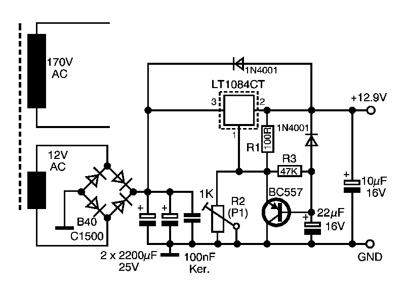
Into the adjustment circuit we include a "something-PNP" transistor (like the common BC557 or suchlike), which bypasses the "lower" resistor R2. Into the base cicuit we include a 47K resistor, which goes to a capacitor. The capacitor charges up via the resistors R1 / R3. The further it charges up, the lesser is the condictive path over the transistor, until it is fully shut at the end of the process and the output voltage is solely determined by R1 / R2 again.
The two 1N4001 diodes take care that the capacitors in the output circuit cannot discharge back into the regulator, when the power supply is switched off. The regulator doesn't like to be feeded backwards.
But now we are in serious trouble. Unfortunately.
Since we are using semiconductor diodes in the anode power supply the anode voltage is already applied long before the tubes are even lightly pre-heated. That's an invalid condition. Here we need to include a circuitry that switches on the anode voltage with a delay. Or else we are going to destroy the tubes - and that is pretty annoying.
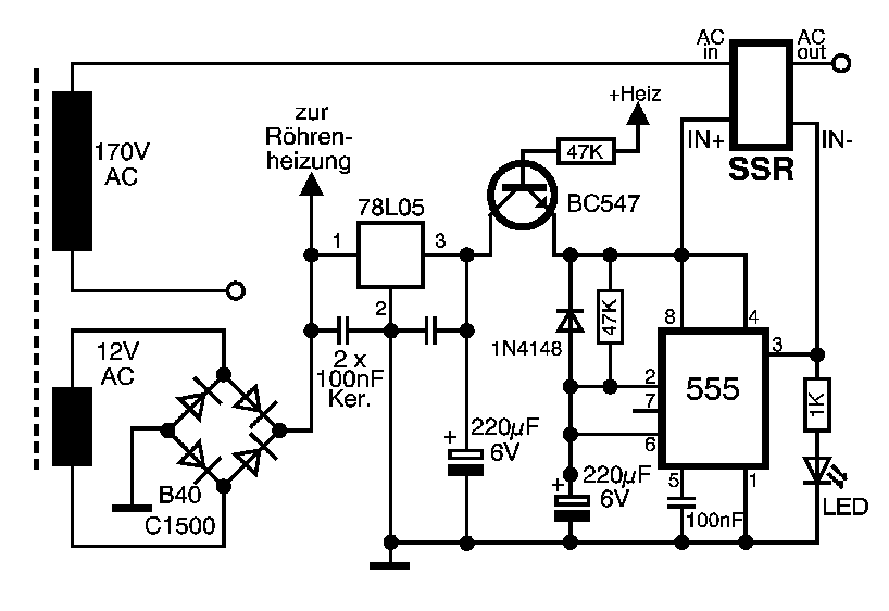
The circuit is pretty easy to explain. My "other favourite IC" is the timer 555.
Okay, okay, I know. You're going to barf and the thing is worth shit, instable and imprecise. I know that. I don't want to achieve a world record in maintaining turn-on times 12 digits behind the decimal dot, but only delay the anode voltage a bit. Around 10 seconds might suffice. That should do until the heater voltage has reached a reasonable level to have the tube heaters already glowing safely.
The 555 is operated as a simple timer. The capacitor charges up, the output changes from High to Low and everything works fine. While the timer is runing a LED signals the waiting time. Once the LED turns off, the anode voltage is switched on. In my case I'd used a "Solid State Relay" (SSR). These have no contacts, don't click, draw 3 - 8 mA current and have no mechanical components that are prone to aging. And they don't need protection diodes over coils.
The SSR simply switches one HV line from the transformer towards the rectifier. And that was is.
The part with the 78L05 - or 7805 or 7808 or whatever - is only there to avoid that the 555 runs above 15 V supply. It cannot stand higher voltages. I took the 78L05 since I have a bag full of them and while +5V is a nice voltage. No need to have a filter cap for the supply voltage if that circuit is fed from the DC heater voltage. There are some big caps already.
If you choose to pick a different voltage you only need to choose the capacitor voltage ranges accordingly. Quite logical, right ?
The part with the transistor and the resistor down from the + of the heater voltage is some sort of "emergency anchor" for the case that the heater circuit goes down for e.g. thermal reason or due to a defect or overload condition. In that case the anode voltage is shut down as well. Cheap, simple, without a microprocessor - but effective. Just for fun you could remove the heatsink from the heater regulator and see when it shuts down.
The cookiebox runs with a circuit like that for weeks already with no problems.
Back to the Cookiebox page
|