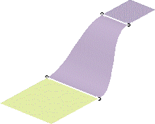
Open the Blend1.CATPart document.
-
Click Blend
 .
.The Blend Definition dialog box appears. 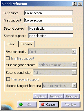
-
Successively select the first curve and its support, then the second curve and its support.
These can be surface edges, or any curve.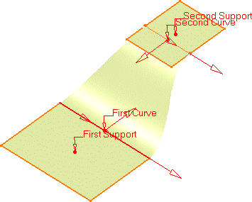
-
Set the continuity type using the Basic tab.
It defines the continuity connection between the newly created surface and the curves on which it lies. The illustration above, shows the Tangency continuity, and the following illustrations show the Point and Curvature continuity types:
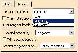
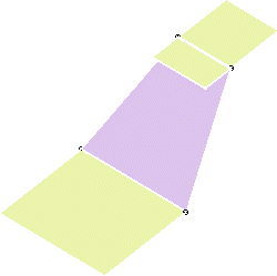
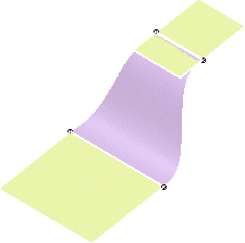
Point continuity on both limits Curvature continuity on both limits -
Check Trim first support/Trim second support, on one or both support surfaces to trim them by the curve and assemble them to the blend surface.
-
Set the tension type using the Tension tab.
It defines the tension of the blend at its limits and can be set for each limit independently
It can be Constant or Linear. A third tension type is available: S Type. It enables to set a variable tension.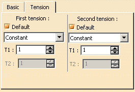
-
Click OK to create the blended surface.
The surface (identified as Blend.xxx) is added to the specification tree. 
- Selecting a support is not compulsory.
- You can create closing points using the contextual menu on the First or Second closing point fields in the dialog box, or using the contextual menu directly on one of the selected curves.
- Use the Replace, Remove, or Reverse buttons, to manage the selected elements (curves, support, closing and coupling points).
- You can also use the contextual menu on the texts displayed on the geometry to set the continuities, trim the supports or manage the curves and support in general.
![]()
